



1
/
of
3
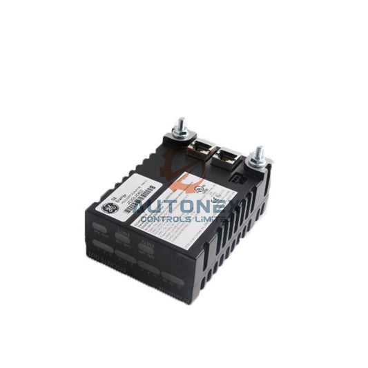
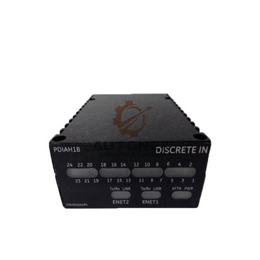
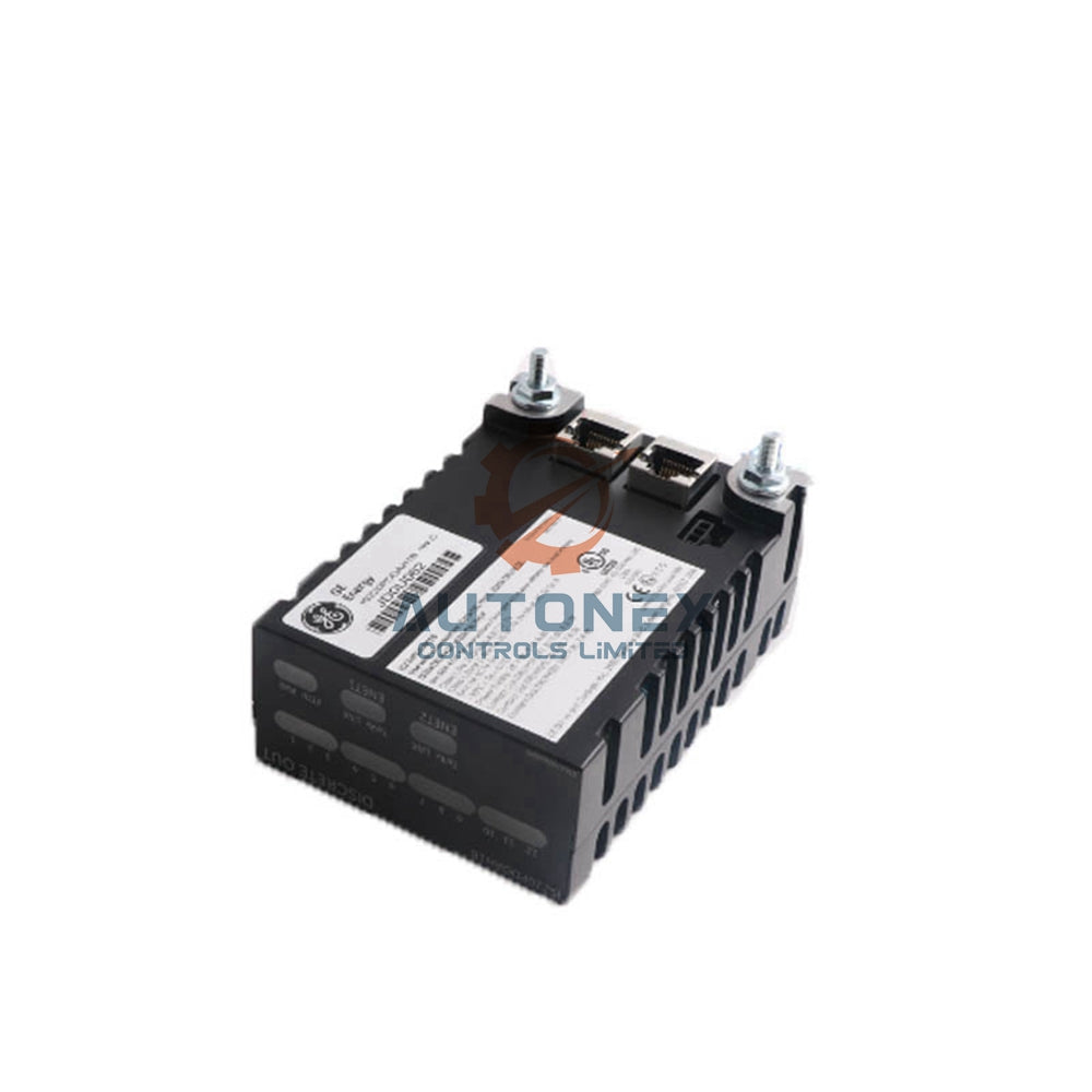
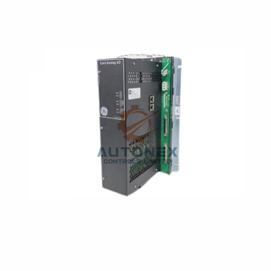
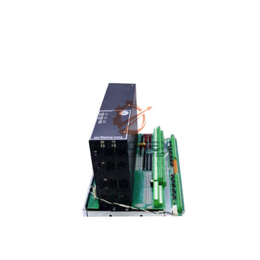
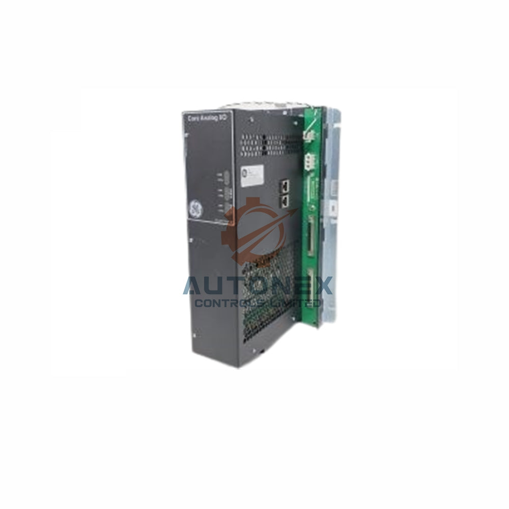
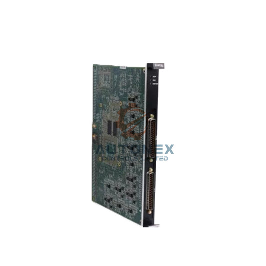
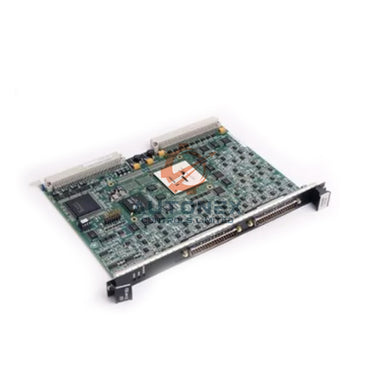
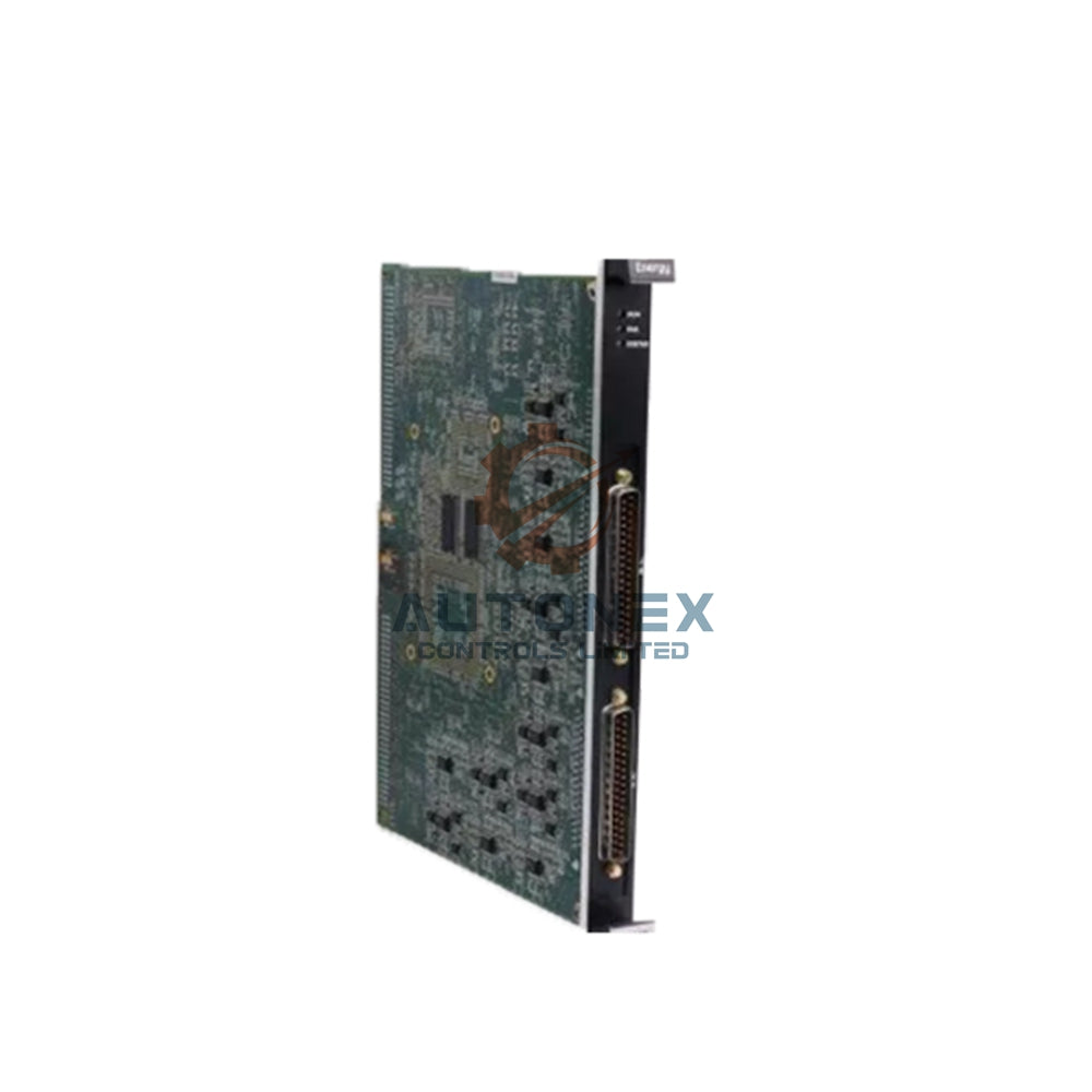
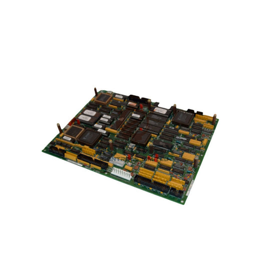
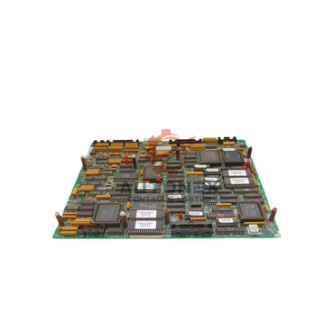
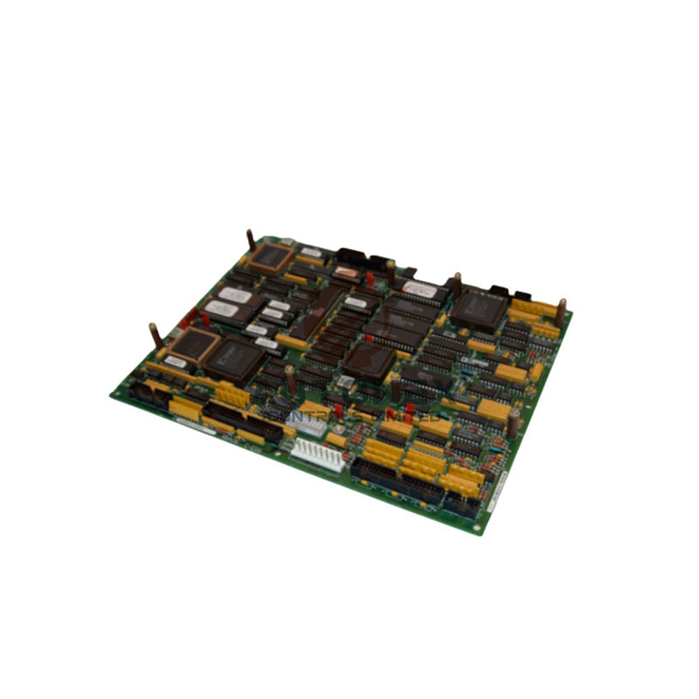
DS200PCCAG6ACB GE Mark V Power Connect Card
No reviews
In stock (14 units), ready to be shipped
-
Vendor:
General Electric
-
Type:
Power Connect Card
-
Country of Origin:
USA
-
Dimensions:
24*16*2.5cm
- Weight:
500 g
- Tags: Power connect card
DS200PCCAG6ACB Power Connect Card for GE Mark V Series
Key Technical Specifications
- Brand: General Electric (GE)
- Model: DS200PCCAG6ACB
- Series: Mark V
- Category: Power Connect Card
- Functional Acronym: PCCA
- Instruction Manual: GEI-100161
- PCB Coating: Normal Coating
- Functional Revisions: A and C
- Artwork Revision: B
- Board Group: Group 6
- Voltage Range: 240 through 700 volts, depending on group type
- Power Conversion: Regenerative and non-regenerative options
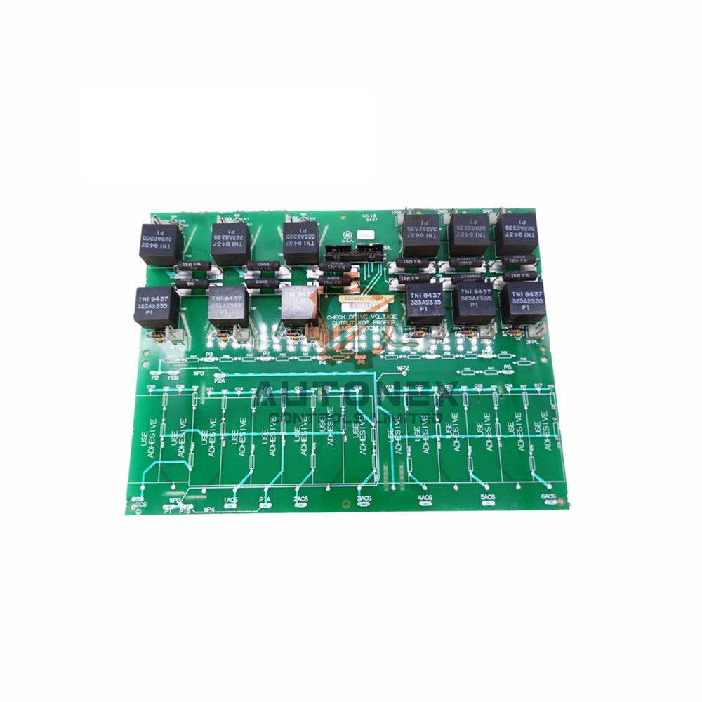
- Connectors: Twelve plug connectors for SCR bridge signals
- On-Board Memory: RAM included
- Country of Manufacture: United States (USA)
Functional Overview
- The board acts as an interface between the drive and the silicon-controlled rectifier power bridge.
- It transmits control signals, commands, and feedback between critical drive components.
- It supports real-time monitoring of current, voltage, and temperature readings.
- It helps regulate power output and voltage levels for stable drive operation.
- It integrates with the drive control circuitry through a standardized interface.
- It minimizes signal loss and interference under various operating conditions.
Group and Voltage Configuration
- Groups 1, 7, and 9 use regenerative power conversion from 240 through 630 volts.
- Groups 2, 8, and 10 use non-regenerative power conversion from 240 through 700 volts.
- Groups 1 and 2, 3 and 4, 5 and 6, 7 and 8, and 9 and 10 share the same application specifications.
- The DS200PCCAG6ACB belongs to group 6.
- Group selection depends on voltage, frame size, and power conversion type.
Snubber Circuits and Horsepower Ratings
- Low-to-medium horsepower controllers include snubber circuits on the board.
- These circuits suppress transient voltage spikes across AC lines, DC bus, and gate drivers.
- They protect semiconductor devices and control circuitry from potential damage.
- Higher horsepower controllers may omit some or all snubber circuits from the PCCA board.
- System designers may relocate those circuits elsewhere in the drive architecture.
- This modular approach optimizes layout, space, and system performance.
Configurable Jumpers
- JP1 and JP2 are wire jumpers that connect to stab terminals P3 through P10.
- Card group number and system voltage determine the correct terminal connections.
- These connections are critical for proper voltage regulation and control.
- WP3 and WP4 connect stab terminals P2A to P2B and P1A to P1B.
- These jumpers select whether snubber capacitors share the same power bridge point as the voltage feedback channel.
- Correct jumper placement ensures effective suppression of voltage spikes and transient disturbances.
Installation Guide
- Verify the card group number and system voltage before installation.
- Set JP1 and JP2 jumpers according to the required stab terminals P3 through P10.
- Configure WP3 and WP4 jumpers based on the snubber capacitor and voltage feedback requirement.
- Connect the twelve plug connectors to the SCR bridge for proper signal transmission.
- Use the control panel or a laptop to set parameters in the configuration file.
- Operators can download the same file to multiple drives or edit a unique configuration for each drive.
- Confirm all connections before applying power to the drive system.
Package List
- 1 x DS200PCCAG6ACB Power Connect Card
- 1 x Anti-static protective packaging
- 1 x Product label and identification tag
Shipping and Availability
- We keep this product in stock for immediate order processing.
- We ship orders within 5 days after payment confirmation.
- We use FedEx, UPS, and DHL for international delivery.
- We support 30-day returns for eligible orders.
- All items are brand new and original.
FAQ
-
Q: What is the DS200PCCAG6ACB used for?
A: It connects the drive control circuitry to the SCR power bridge in GE Mark V systems. -
Q: Which board group does this card belong to?
A: This card belongs to group 6. -
Q: What voltage range does this board support?
A: It supports 240 through 700 volts, depending on the group and conversion type. -
Q: Does this card include snubber circuits?
A: Low-to-medium horsepower controllers include them, while higher horsepower designs may relocate or omit them. -
Q: How do I configure JP1 and JP2?
A: Connect them to stab terminals P3 through P10 based on card group and system voltage. -
Q: What do WP3 and WP4 jumpers control?
A: They select whether snubber capacitors connect to the same power bridge point as the voltage feedback channel. -
Q: Is this product new and original?
A: Yes, we supply brand new original products. -
Q: How fast do you ship?
A: We ship within 5 days using FedEx, UPS, or DHL. -
Q: Do you accept returns?
A: Yes, we support 30-day returns.
Contact Information
- Inquiries: sales@nex-auto.com
- Phone/WhatsApp: +86 153 9242 9628
- Partner NexAuto Technology Limited: https://www.nex-auto.com/
Fast & Reliable Shipping
Quick worldwide delivery
keeps your automation projects on schedule.
Genuine & Trusted
All components are 100% authentic
ensuring reliable performance for your systems.
- Express Delivery
- 12 Months Warranty
- 30 Days Easy Returns


Customer Support
Get Help When You Need It Most
Here to Assist Your Automation Needs
Contact us for pricing, product details, or order assistance — our experts are available to help.
Know Your Return Rights
You have 30 days to return a product if it doesn’t meet your requirements. See the full policy for details.