



IC693CBK001 Termination Resistors: The Hidden Cause of Intermittent Expansion Rack Failures in GE Series 90-30 PLC Systems
Industrial automation engineers often overlook a small but critical component in GE Series 90-30 PLC backplane systems. That component is the termination resistor. Consequently, mysterious intermittent faults appear in expansion racks. This article explores the root cause, diagnostic methods, and field-proven solutions.
Why Termination Resistors Matter in PLC Backplane Communication
The I/O expansion bus in GE Series 90-30 systems acts as a high-speed serial link. Therefore, each signal pair needs proper termination. Specifically, six signal pairs require 120-ohm, quarter-watt resistors at the final backplane. These pairs sit on pins 16-17, 24-25, 20-21, 12-13, 8-9, and 2-3.
Without termination, signal reflections corrupt data transmission. As a result, the CPU loses communication with expansion modules. Field data shows that rates above 38.4 kbps become especially vulnerable. This issue affects factory automation and control systems across many industries.
How IC693CBK001 Relates to Termination Practice
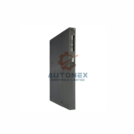
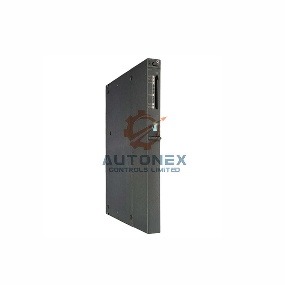
The IC693CBK001 kit contains two high-density I/O cables with 24-pin connectors. However, this kit serves 32-point I/O modules, not the expansion bus. The termination resistor function is handled separately by the IC693ACC307 terminator plug. In addition, the IC693CBL302 15-meter cable includes built-in terminating resistors at one end.
Engineers must understand this distinction. Otherwise, they may install the wrong part and leave the bus unterminated. This mistake leads to random faults that are hard to diagnose.

Random Faults Caused by Missing Termination Resistors
When the terminator pack is absent, signal reflections corrupt the expansion bus waveform. Consequently, the CPU intermittently loses communication with expansion modules. Field experience shows that data transmission rates above 38.4 kbps become especially vulnerable to these reflections.
These faults appear random and unpredictable. Therefore, many technicians waste hours replacing good modules. In reality, the problem lies in the missing termination.
Documented Failure Symptoms in Industrial Automation
Specific fault logs reveal a clear failure pattern. The CPU records "Loss of I/O Module" faults when a previously present module stops responding. Subsequently, "Addition of I/O Module" faults appear when the scanner detects unexpected addresses. Eventually, accumulated configuration mismatches force the CPU into STOP mode.
This sequence repeats across different control systems. As a result, production downtime increases. Moreover, troubleshooting becomes complex without proper diagnostic data.
Statistical Failure Patterns from the Field
Field experience indicates that approximately 90% of communication problems with extensions stem from poor seating or cable stress. Nevertheless, missing termination accounts for a significant portion of remaining failures. One documented case involved module dropouts occurring every 15 minutes, escalating to hard STOP within hours.
These statistics highlight the importance of proper installation. In addition, they show that simple checks can prevent major disruptions.
Diagnostic Verification Methods for Engineers
Engineers can verify termination presence through voltage and resistance measurements. Between bus pins A and B, a properly terminated segment should show approximately 1.1 volts. Furthermore, the resistance measurement should approach 220 ohms.
These measurements provide quick confirmation. Therefore, technicians can identify missing terminators before they cause system-wide failures. This approach saves time and reduces spare parts costs.
Consequences for Multi-Rack Configurations
Systems with multiple expansion racks face heightened risk. The maximum cable length between the CPU baseplate and the last expansion baseplate reaches 15 meters. Additionally, CPUs 331-341 support a maximum of four expansion cables. Conversely, CPUs 350-374 accommodate up to seven cables.
Longer cables and more racks increase signal reflection risk. As a result, proper termination becomes even more critical. Engineers should always check the final baseplate in the chain.
Best Practices for Termination Installation
Only the final baseplate in the expansion chain requires the terminator plug. Each baseplate ships with one IC693ACC307 terminator. Unused terminators serve as spare parts. When using the IC693CBL302 cable, built-in resistors eliminate the need for a separate terminator pack.
Moreover, engineers should document termination locations. This practice helps future maintenance and reduces downtime. In addition, regular inspections can catch loose or missing terminators early.
Summary of Critical Specifications
The termination resistor value remains fixed at 120 ohms with 0.25-watt power rating. These resistors terminate six specific signal pairs across designated pins. Proper termination prevents signal reflection, maintains data integrity, and ensures reliable CPU-to-expansion communication.
Therefore, industrial automation professionals should treat termination as a first-line diagnostic check. This simple step can resolve many intermittent faults in PLC and DCS systems.

Application Case: Solving a Real-World Factory Automation Problem
A manufacturing plant experienced random stoppages on a GE Series 90-30 system. The CPU logged "Loss of I/O Module" faults every 15 minutes. Technicians replaced cables and modules without success. Eventually, they measured resistance between bus pins A and B. The reading was open circuit, indicating missing termination. After installing the IC693ACC307 terminator plug, the faults disappeared completely.
This case demonstrates the value of systematic diagnostics. Moreover, it shows how a low-cost component can prevent costly downtime.
Frequently Asked Questions
Q1: What is the purpose of a termination resistor in a PLC backplane?
A1: It prevents signal reflections on the high-speed serial link. Without it, data corruption and intermittent faults occur.
Q2: How can I check if my GE Series 90-30 expansion bus is properly terminated?
A2: Measure voltage between pins A and B. A reading near 1.1 volts indicates proper termination. Also, resistance should be about 220 ohms.
Q3: Does the IC693CBK001 kit include termination resistors?
A3: No. The IC693CBK001 kit contains I/O cables for 32-point modules. Termination is handled by the IC693ACC307 plug or the IC693CBL302 cable.
Q4: What happens if I forget to install the terminator plug?
A4: The CPU may intermittently lose communication with expansion modules. Fault logs show "Loss of I/O Module" and "Addition of I/O Module" errors. Eventually, the CPU may enter STOP mode.
Q5: Can I use any 120-ohm resistor for termination?
A5: Use only the specified 120-ohm, quarter-watt resistors. They must connect to the six designated signal pairs. Improper resistors may not prevent reflections effectively.
Contact Information
For inquiries, please contact us:
Email: sales@nex-auto.com
Phone/WhatsApp: +86 153 9242 9628
Partner: NexAuto Technology Limited
Website: https://www.nex-auto.com/
Check below popular items for more information in AutoNex Controls

