

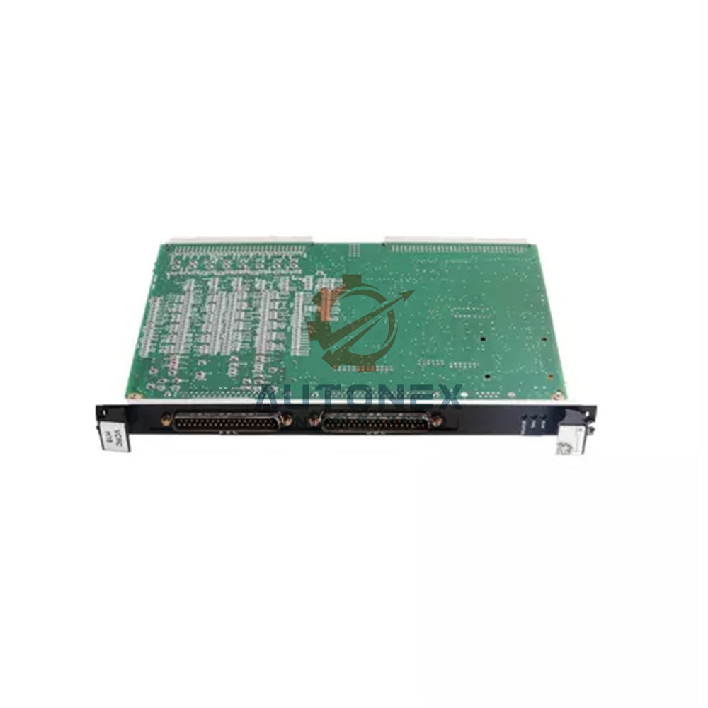
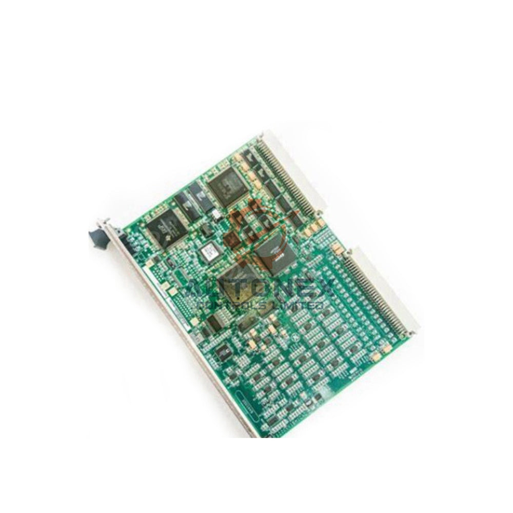


Missing IC693ACC307 Terminator: Why Digital I/O Stays Stable While Analog Data Oscillates
Field engineers in industrial automation often report a strange split in behavior. Digital I/O keeps working, yet analog readings swing wildly. The missing IC693ACC307 bus terminator on a Series 90-30 expansion chain is a common root cause. This article explains the physics, the thresholds, and a practical check before analog loops enter control service.
The Terminator’s Role in the Series 90-30 I/O Bus
What the IC693ACC307 Actually Does
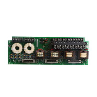
The IC693ACC307 is a passive resistor pack inside a 25-pin connector. It mounts only on the final baseplate of an expansion chain. Each signal pair needs termination to match the bus characteristic impedance. Without matching, incident energy reflects at the open end.
How Reflections Distort Bus Transactions
The reflected wave superimposes on the original waveform. This superposition distorts rising and falling edges of every bus transaction. Distortion grows with cable length and data rate. Series 90-30 systems above 38.4 kbps are especially vulnerable to reflection-induced corruption.
Why Digital Signals Survive an Unterminated Bus
Broad Thresholds and Generous Timing Margins
Digital I/O modules tolerate waveform distortion well. Their decision thresholds are broad and timing margins are generous. A reflected wave may cause overshoot or ringing at the receiver. However, the digital value is captured correctly if the signal settles before sampling.
Short Data Bursts Hide the Problem
Most discrete transactions on the Series 90-30 backplane are short data bursts. These bursts complete well within the scan cycle. As a result, an unterminated bus often passes digital data without visible errors. Field observations confirm digital functions may remain stable for extended periods.
The Analog Module’s Sensitivity to Bus Reflections
Multi-Bit Words Demand Every Bit Intact
Analog modules place a fundamentally different burden on the backplane bus. Each analog value is a multi-bit word. The module must transfer this word with every bit intact. A single corrupted bit in a 12-bit or 16-bit word produces a numeric error the CPU reads as a real process change.
Why Analog Readings Jump Between Erroneous Values
When reflections corrupt successive bus cycles, the analog reading jumps between erroneous values. The result is the large-amplitude fluctuation seen in the data table. This is not a sensor problem. It is a communication integrity problem manifesting as analog instability. The narrower the input range, the more pronounced the visible fluctuation.

Quantifying the Failure: Cable Length and Data Rate Thresholds
Propagation Delay Versus Signal Rise Time
Reflection severity depends on the ratio of cable propagation delay to signal rise time. Series 90-30 expansion cables reach 15 meters per segment. At this length, an unterminated bus shows pronounced impedance mismatch at the open connector. The reflection coefficient approaches +1, meaning nearly full amplitude reflection occurs.
Field Failure Data and Escalation Patterns
Field data indicates about 90% of extension communication problems stem from seating or cable stress issues. Missing termination accounts for a substantial portion of the remaining failures. In one documented case, module dropouts occurred every 15 minutes and escalated to a hard CPU stop within hours. Analog channels in such systems typically show instability before the CPU registers a bus fault.
Distinguishing Termination Faults from Analog Wiring Problems
The Distinctive Signature of a Termination Fault
Engineers frequently misdiagnose analog fluctuation as a grounding or shielding defect. Common causes include disconnected sensor commons, excessive cable runs, or inadequate common-mode rejection. However, a termination-related fault has a distinctive signature. The fluctuation appears simultaneously across multiple analog channels in the same expansion rack. It correlates with CPU scan activity rather than process changes. Digital modules in the same rack continue to report stable states.
A Quick Resistance Check
This pattern points to the backplane rather than field wiring. A quick verification involves measuring resistance across the bus termination pins. A properly terminated segment should measure approximately 220 ohms. Therefore, this simple check separates a backplane issue from a field wiring issue.
Correct Installation Practice and Diagnostic Verification
Where the Terminator Belongs
Only the last baseplate in the expansion chain requires the IC693ACC307 terminator. Intermediate baseplates must not carry the terminator. When the IC693CBL302 cable is used for a single 15-meter expansion link, the cable’s built-in termination eliminates the need for a separate terminator plug. For all other configurations, the terminator must be physically seated in the open connector of the final baseplate.
Pass/Fail Measurements Before Commissioning
A voltage measurement between bus pins A and B should read approximately 1.1 volts on a healthy terminated segment. Resistance across the same pins should approach 220 ohms. These two measurements provide a definitive pass/fail check before analog loops are placed in service. In addition, record both values in the commissioning documentation for future reference.
Operational Consequences and Recommended Actions
How Corrupted Readings Propagate
An unterminated analog bus does not fail gracefully. The corrupted readings propagate into control algorithms, PID loops, and trend displays. Operators may respond to phantom process excursions. Maintenance personnel may replace perfectly functional analog modules, sensors, and transmitters in a futile cycle.
A Five-Minute Corrective Action
The corrective action is simple and inexpensive. Verify that the final baseplate carries an IC693ACC307. Confirm that no intermediate baseplate has one installed. Measure the termination resistance at the bus end. Record the measurement in the commissioning documentation. These steps require less than five minutes and eliminate a class of faults that can consume days of troubleshooting effort.

Author Insight: Why This Fault Persists in Factory Automation
Digital Stability Creates False Confidence
In my experience supporting PLC and DCS installations, digital stability creates false confidence. Technicians see healthy discrete signals and rule out the backplane. However, analog channels tell a different story. The asymmetry is a useful diagnostic clue, not a coincidence. Moreover, this fault class is easy to prevent during commissioning and easy to miss during routine maintenance.
Termination Checks Belong in Commissioning Checklists
I recommend adding termination verification to every factory automation commissioning checklist. The measurement takes seconds and the payoff is significant. As a result, teams avoid phantom analog excursions and unnecessary module replacements. This practice also strengthens control system reliability before PID loops go live.
Application Case and Solution Scenario
Scenario: Multiple Analog Channels Fluctuating in One Rack
A water treatment plant reported simultaneous fluctuation on four analog input channels in one expansion rack. Digital modules in the same rack remained stable. The fluctuation correlated with CPU scan activity, not with process changes. The team measured resistance across the bus termination pins and found an open circuit. The final baseplate was missing the IC693ACC307 terminator.
Resolution and Verification
The team installed the terminator on the last baseplate and confirmed no intermediate baseplate carried one. They then measured 220 ohms across the termination pins and about 1.1 volts between pins A and B. Analog readings stabilized immediately. As a result, the plant avoided replacing sensors and transmitters. The team added the resistance check to its preventive maintenance schedule.
Frequently Asked Questions
Why do digital I/O modules work without the IC693ACC307 terminator?
Digital modules have broad decision thresholds and generous timing margins. Short data bursts complete within the scan cycle. Therefore, reflected energy rarely corrupts a discrete value before sampling.
Where should the IC693ACC307 terminator be installed?
Install it only on the final baseplate of the expansion chain. Intermediate baseplates must not carry a terminator. When using the IC693CBL302 cable for a single 15-meter link, the cable’s built-in termination replaces the separate plug.
What resistance and voltage should a healthy terminated segment show?
A healthy segment measures approximately 220 ohms across the bus termination pins. The voltage between pins A and B should read approximately 1.1 volts. Record both values during commissioning.
How can I tell a termination fault from an analog wiring problem?
Termination faults affect multiple analog channels in the same rack at once. They correlate with CPU scan activity rather than process changes. Digital modules in the same rack usually remain stable. A resistance check across the termination pins confirms the diagnosis.
Can a missing terminator cause a CPU stop?
Yes. In one documented case, module dropouts occurred every 15 minutes and escalated to a hard CPU stop within hours. Analog instability typically appears before the CPU registers a bus fault.
