



1
/
of
3
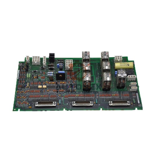
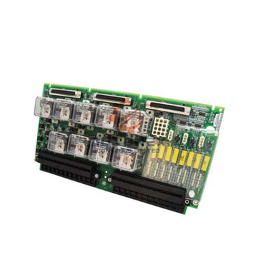
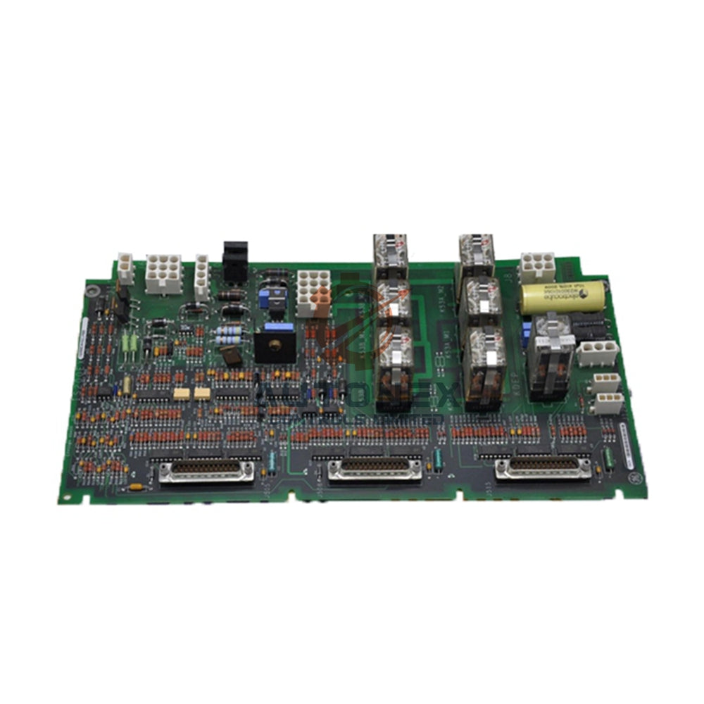
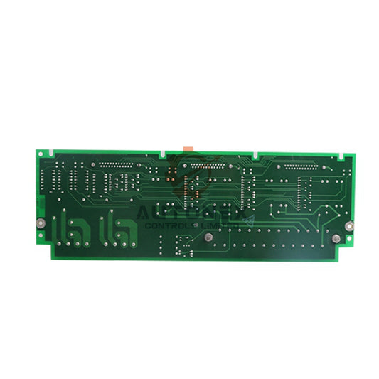
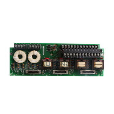
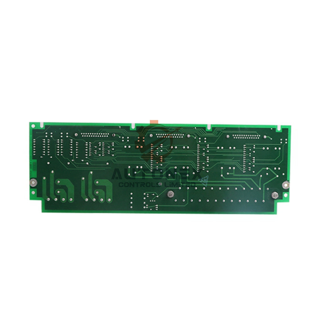
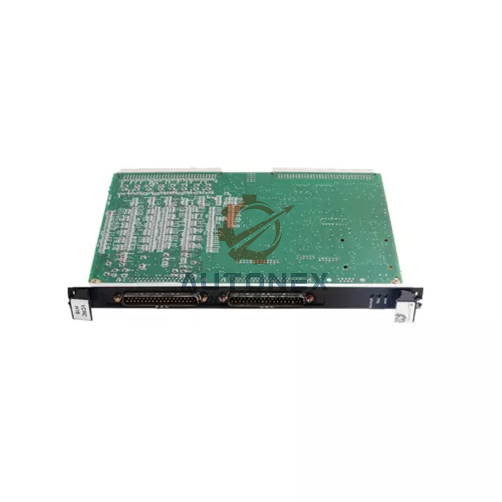
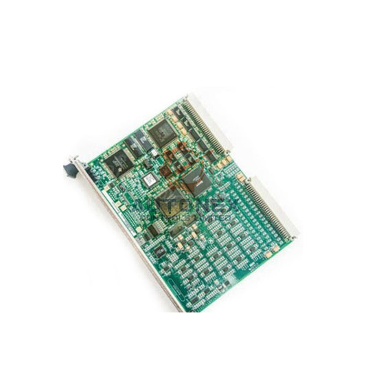
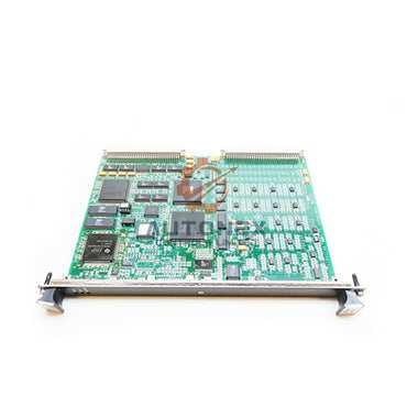
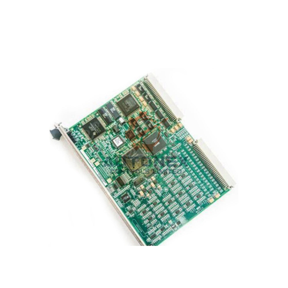
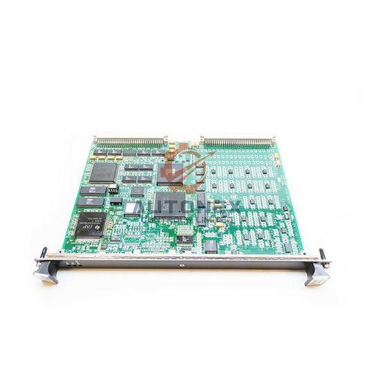
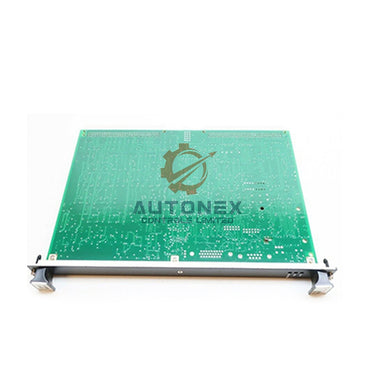
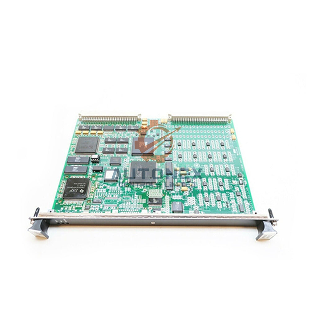
IS210TRPGH1B GE Mark Vle Primary Trip Terminal Board
No reviews
In stock (14 units), ready to be shipped
-
Vendor:
General Electric
-
Type:
Terminal Board
-
Country of Origin:
USA
-
Dimensions:
25*18*4cm
- Weight:
500 g
- Tags: Terminal board
IS210TRPGH1B GE Mark Vle Primary Trip Terminal Board – Product Introduction
Technical Specifications
- Brand: General Electric (GE)
- Model: IS210TRPGH1B
- Category: Primary Trip Terminal Board
- Series: Mark Vle
- Trip Solenoids: 3 solenoids (Electrical Trip Devices)
- Solenoid Rated Voltage/Current: 125 V dc
- Solenoid Response Time: L/R time
- Current Suppression: Metal oxide varistor
- Control Relay Coil Voltage Supply: 28 V
- Flame Detector Supply Voltage/Current: 335 V dc
- Flame Detectors: 8 units
- Magnetic Relays: Nine relays in three voting circuits
- Manual: GEH-6721J
- Country of Origin: United States
- Availability: In stock
Functional Overview
- The I/O controller manages the TRPG terminal board during operation.
- The TRPG board contains nine magnetic relays across three voting circuits.
- These circuits interface with three trip solenoids, also called Electrical Trip Devices.
- The TRPG works with the TREG board to serve the primary and emergency ETD sides.
- The board accommodates inputs from eight Geiger Mueller flame detectors for gas turbines.
- The H1A and H1B versions include three voting relays built into each trip solenoid for TMR applications.
- PTUR packs on the TTURH1C control the TRPG in Mark Vle systems.
- The D-type connectors on the TTURH1C accept the I/O packs as an input.
- Simplex and TMR systems both receive full support.
Installation Guide
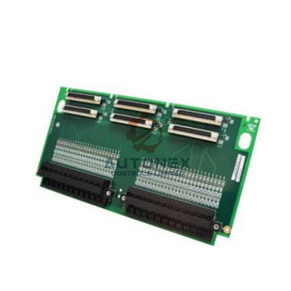
- Attach the flame detectors (if used) directly to the second terminal block.
- Wire the three trip solenoids to the first I/O terminal block.
- Link the flame detectors with power to J3, J4, and J5.
- Feed 125 V dc power for the trip solenoids into J1.
- Supply power to the TREG board through J2.
- Follow the procedures in manual GEH-6721J for complete installation steps.
- Treat the board as static-sensitive and use anti-static protection during handling.
Operation Details
- The main protection relays on the TRPG trip the main protection solenoids.
- The I/O board controls these protection relays during normal operation.
- In TMR applications, a relay ladder logic two-out-of-three voting circuit votes the three inputs in hardware.
- The I/O board tracks supply voltages for diagnostic purposes.
- It tracks current flow in its relay driver control line to set relay coil contact status.
- The diagnostics check each normally closed relay contact for proper function.
- The controller transmits the primary overspeed trip to the I/O pack or board.
- The signal then reaches the TRPG terminal board for action.
- Together with the TREG board, the TRPG works under the VPRO emergency overspeed system.
- The TRPG and TREG combination may drive three ETDs.
Packing List
- One IS210TRPGH1B Primary Trip Terminal Board
- Anti-static protective packaging material
- Original GE manual reference GEH-6721J where available
- Shipping through FedEx, UPS, or DHL
FAQ
-
Q: What is the condition of this board?
A: We supply brand new original units. -
Q: Do you have stock available?
A: Yes, we hold this item in stock. -
Q: How fast do you ship?
A: We dispatch within 5 days of your order. -
Q: Which logistics partners do you use?
A: We ship through common carriers such as DHL, FedEx, and UPS. -
Q: Can I return the product?
A: Yes, we support returns within 30 days. -
Q: How many trip solenoids does the IS210TRPGH1B support?
A: It interfaces with three trip solenoids, also called Electrical Trip Devices. -
Q: What voltage do the trip solenoids use?
A: The trip solenoids use a rated 125 V dc. -
Q: How many flame detectors does the board accept?
A: It accepts inputs from eight Geiger Mueller flame detectors. -
Q: What is the flame detector supply voltage?
A: The flame detector supply runs at 335 V dc. -
Q: What voltage supplies the control relay coil?
A: The control relay coil uses a 28 V supply. -
Q: How does the board suppress current?
A: It uses a metal oxide varistor for current suppression. -
Q: Which manual covers this board?
A: Manual GEH-6721J covers the board. -
Q: Does the board support TMR systems?
A: Yes, it supports both simplex and TMR systems.
Fast & Reliable Shipping
Quick worldwide delivery
keeps your automation projects on schedule.
Genuine & Trusted
All components are 100% authentic
ensuring reliable performance for your systems.
- Express Delivery
- 12 Months Warranty
- 30 Days Easy Returns


Customer Support
Get Help When You Need It Most
Here to Assist Your Automation Needs
Contact us for pricing, product details, or order assistance — our experts are available to help.
Know Your Return Rights
You have 30 days to return a product if it doesn’t meet your requirements. See the full policy for details.