



1
/
of
3
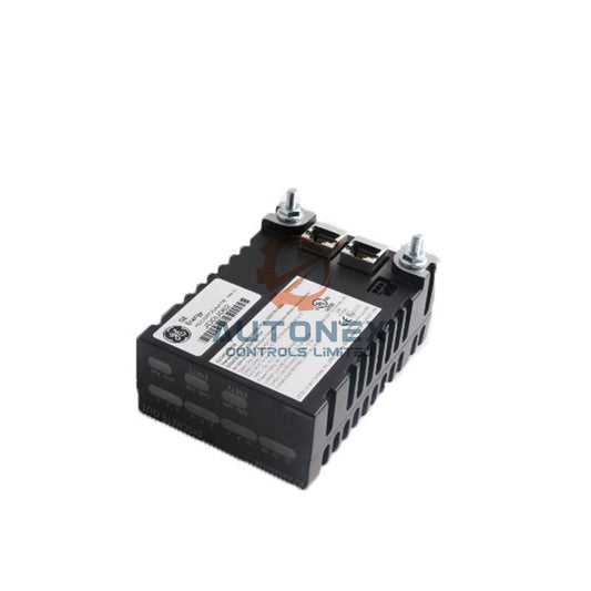
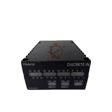
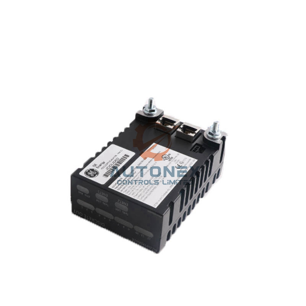
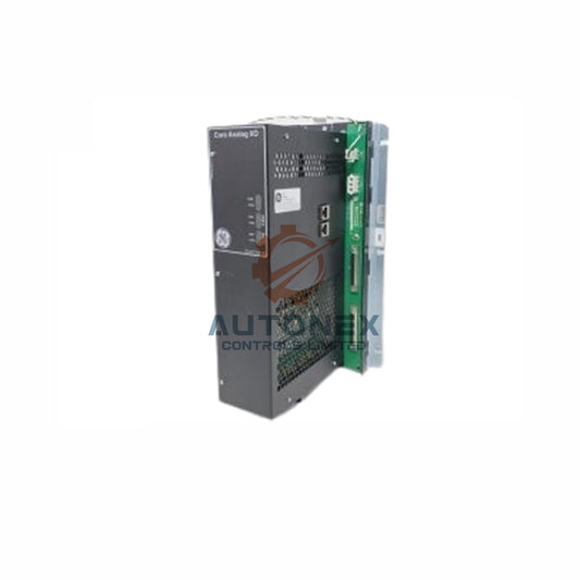
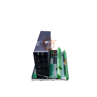
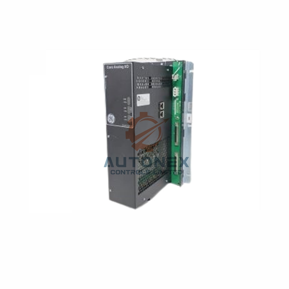
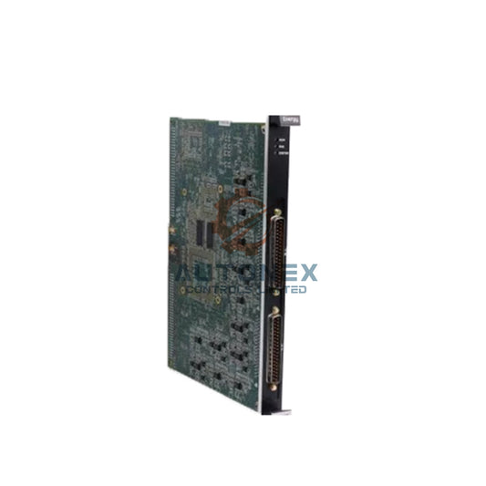
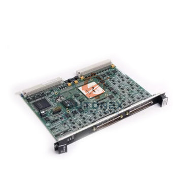
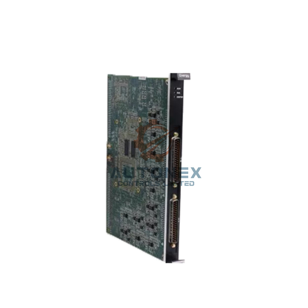
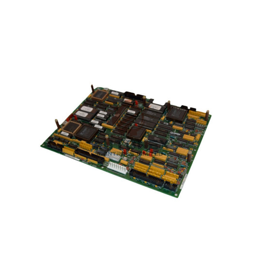
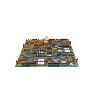
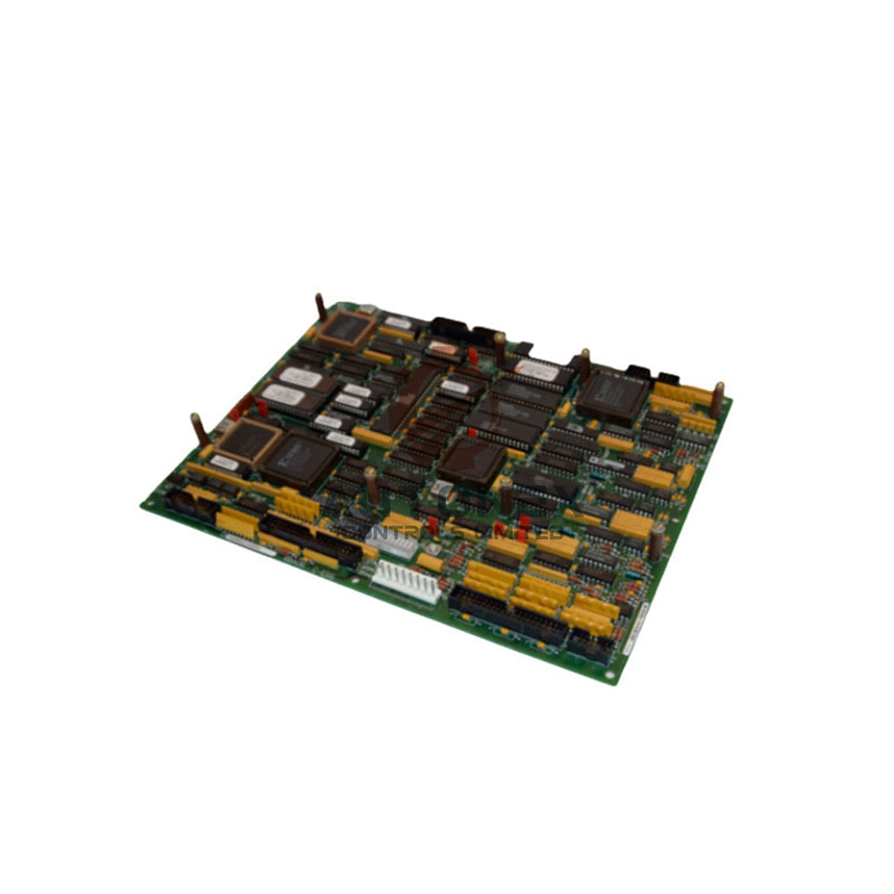
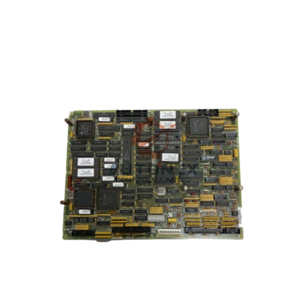
DS200PTCTG1BAA General Electric Mark V PT CT Signal Conditioner Board
No reviews
In stock (14 units), ready to be shipped
-
Vendor:
General Electric
-
Type:
Signal Conditioner Card
-
Country of Origin:
USA
-
Dimensions:
29*5*5cm
- Weight:
500 g
- Tags: Signal conditioner card
DS200PTCTG1BAA Potential Transformer Current Transformer – General Electric Mark V Signal Conditioner Board
Technical Specifications
- Brand: General Electric
- Model: DS200PTCTG1BAA
- Series: Mark V
- Category: PT and CT Signal Conditioner Board
- Functional Acronym: PTCT
- Functional Description: Signal Conditioner Card
- Power Requirements: +5 V dc, 6 A
- Input Voltage: 120 V AC
- Power Supply Voltage: 24 V dc
- Power System Frequency: 60 Hz
- Number of Relay Channels: 12
- Mounting: DIN-rail mounting
- Technology: Surface mount
- Operating Temperature: -30 to +65°C
- Size: 15.9 cm high x 17.8 cm
- PCB Coating: Normal Coating
- Revision Quantity: 3 Revisions
- Assembly Type: Normal Assembly
- Mark V Series Grouping: Group 1
- Country of Origin: United States
- Availability: In Stock
Key Functions and Signal Conditioning
- Signal Isolation: The board provides galvanic isolation between high voltage circuits and low voltage control circuits. This design protects sensitive equipment and personnel from dangerous electrical exposure.
- Surge Protection: The DS200PTCTG1BAA safeguards itself and downstream devices from transient overvoltages. This protection supports stable operation in demanding turbine control environments.
- Amplification: It raises incoming signal levels to an optimal range for A/D converters and other processing hardware.
- Filtering: The board removes noise and unwanted frequency components. This process delivers a clean and stable signal for control and measurement tasks.
- Linearization: The output signal remains directly proportional to the input signal across the specified operating range.
- Analog-to-Digital Conversion: It converts analog PT and CT signals into digital format for digital protection relays or data acquisition systems.
- Calibration and Adjustment: Built-in potentiometers or digital settings calibrate gain, offset, and other parameters. This feature ensures accurate signal processing.
Hardware and Connector Details
- The TCCB Board plays a crucial role by accepting secondary isolation transformers through the attached JKK connector.
- The assembly uses voltage-limiting components such as Mark V rectifiers, capacitors, diodes, and integrated circuits.
- This signal conditioner board includes 1 terminal block with terminals for 72 signal wires.
- It also contains 1 50-pin connector for system integration.
- Terminal block IDs include OUT2, OUT1, COM1, COM2, P15, SO21, and L23.
- The board also provides terminal posts for 6 signal wires.
- The original performance specifications and dimensions reflect a B-rated primary revision, an A-rated secondary revision, and an A-rated artwork revision.
Installation and Interference Reduction Guide
- Plan cable routing carefully before you install the drive and connect the board.
- Route high-voltage power cables away from signal cables whenever possible.
- Bundle power cables together and bundle signal cables together as separate groups.
- Limit the length where power and signal cables run in parallel.
- Keep signal and power cables further apart when parallel runs are longer.
- Allow closer spacing when parallel runs are shorter.
- Run signal and power cables at right angles to reduce signal exposure to interference.
- Use shielded cables under some conditions to protect signal wires from interference.
Performance and Environmental Capabilities
- Measurement Range: The board conditions PT and CT signals for voltage and current measurement in Mark V drive systems.
- Frequency Response: It supports a 60 Hz power system frequency for compatible turbine control applications.
- Sensitivity: The signal conditioner adapts low-level PT and CT signals for accurate processing by control hardware.
- Linearity: The output remains proportional to the input over the specified operating range.
- Resolution: Analog-to-digital conversion prepares signals for digital relays and data acquisition systems.
- Temperature Range: The board operates reliably from -30 to +65°C.
- Environmental Tolerance: Normal PCB coating helps the board resist common industrial operating conditions.
- Anti-Interference Ability: Proper cable routing, bundling, right-angle crossing, and shielding reduce signal interference.
Installation Notes
- Use DIN-rail mounting for secure placement inside the compatible Mark V drive assembly.
- Confirm the power requirements of +5 V dc, 6 A before you connect the board.
- Verify the 120 V AC input voltage and 24 V dc power supply voltage for proper system matching.
- Check all terminal block connections for OUT2, OUT1, COM1, COM2, P15, SO21, and L23.
- Inspect the 50-pin connector and JKK connector for secure attachment.
- Follow the original instructional manual for cable planning and interference control.
Packaging List
- 1 x DS200PTCTG1BAA Potential Transformer Current Transformer board
- 1 x Protective packaging for safe transit
- 1 x Anti-static wrapping for electronic component protection
- 1 x Order documentation package without certificate information
Shipping and Support
- We keep this item in stock and dispatch it within 5 days after order confirmation.
- We ship by common express methods such as FedEx, UPS, and DHL.
- We support 30-day returns under our stated return policy.
- All items are brand new and original.
FAQ
-
Q: What is the model number of this General Electric board?
A: The model number is DS200PTCTG1BAA, and it belongs to the Mark V series. -
Q: What does this board do in a Mark V system?
A: It scales and isolates PT and CT signals while providing auxiliary inputs and outputs for low voltage drive signals. -
Q: What are the power requirements?
A: The board requires +5 V dc at 6 A, with a 24 V dc power supply voltage. -
Q: What is the input voltage and frequency?
A: The input voltage is 120 V AC, and the power system frequency is 60 Hz. -
Q: What is the operating temperature range?
A: The board operates from -30 to +65°C. -
Q: How many relay channels does it have?
A: It has 12 relay channels for compatible control applications. -
Q: How does the board reduce signal interference?
A: Proper cable routing, bundling, right-angle crossing, and shielded cables help reduce interference. -
Q: What connectors and terminals does it include?
A: It includes 1 terminal block for 72 signal wires, 1 50-pin connector, and terminal posts for 6 signal wires. -
Q: What is the mounting type?
A: The board uses DIN-rail mounting for installation in compatible Mark V assemblies. -
Q: Is this item in stock, and how fast do you ship?
A: Yes, we keep it in stock and ship within 5 days using FedEx, UPS, or DHL.
Contact Information Inquiries: sales@nex-auto.com or +86 153 9242 9628
Partner NexAuto Technology Limited: https://www.nex-auto.com/
Fast & Reliable Shipping
Quick worldwide delivery
keeps your automation projects on schedule.
Genuine & Trusted
All components are 100% authentic
ensuring reliable performance for your systems.
- Express Delivery
- 12 Months Warranty
- 30 Days Easy Returns


Customer Support
Get Help When You Need It Most
Here to Assist Your Automation Needs
Contact us for pricing, product details, or order assistance — our experts are available to help.
Know Your Return Rights
You have 30 days to return a product if it doesn’t meet your requirements. See the full policy for details.