


Decoding SMC20 LED Indicators for Sinamics S120 Drive Systems
Understanding the Sensor Module Cabinet-Mounted SMC20
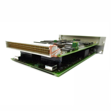
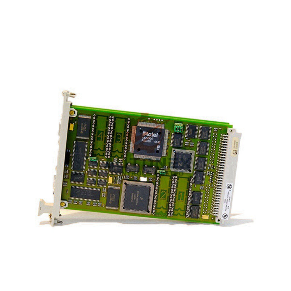
The Siemens SMC20 module processes encoder signals for Sinamics S120 drives. It transmits critical motor data through DRIVE-CLiQ communication. Proper LED interpretation enables quick fault identification and resolution.
RDY LED: Power and Communication Status
No illumination indicates missing power supply. Solid green confirms normal operation with active communication. Orange light shows DRIVE-CLiQ connection establishment. Continuous red signals active faults requiring immediate attention.
Firmware Update Indicators
Slow green-red flashing (0.5 Hz) indicates ongoing firmware transfer. Faster flashing (2 Hz) means download completion awaiting power cycle. Always follow manufacturer procedures during updates to prevent system corruption.

Component Recognition Mode
Combined color flashing (green-orange or red-orange) activates component identification. This feature helps technicians locate specific modules within complex drive systems during maintenance procedures.
Troubleshooting Common SMC20 Faults
Red LED illumination requires fault removal and acknowledgment. Check power quality and DRIVE-CLiQ cable connections first. Consult Siemens documentation for specific error codes and resolution steps.
Maintenance Best Practices
Regularly inspect LED status during system operation. Document unusual patterns for preventive maintenance. Keep firmware updated according to Siemens recommendations for optimal performance.
Technical Documentation Reference
Always consult SINAMICS S120 Commissioning and List Manuals for detailed fault information. These resources provide comprehensive guidance beyond basic LED interpretation for complex drive scenarios.
Application Example: Automotive Production Line
A motor conveyor system showed intermittent SMC20 red LED activation. Investigation revealed loose DRIVE-CLiQ connectors. Securing connections and updating firmware resolved the instability issues.
Expert Insight: Drive System Diagnostics
Modern drive systems rely heavily on module communication integrity. The SMC20's LED indicators provide first-level diagnostics that can prevent costly downtime when properly understood and acted upon.

FAQs: SMC20 Operation
What does continuous red RDY LED indicate?
This signals active faults within the module. Remove power, check connections, and restart. Persistent red requires detailed fault code investigation.
How long should firmware updates take?
Typical SMC20 firmware downloads complete within 5-10 minutes. Do not interrupt power during the green-red flashing sequence.
Can LED colors indicate communication quality?
While LEDs show communication status, detailed quality metrics require diagnostic software tools for comprehensive analysis.
What causes orange RDY LED to remain lit?
Permanent orange suggests DRIVE-CLiQ communication establishment failure. Check network configuration and cable integrity.
How critical are SMC20 status indicators?
These LEDs provide essential health monitoring for critical motor control functions. Regular observation forms part of basic drive maintenance.
Check below popular items for more information in Autonexcontro

