




IC693CBL327/328 Intermittent Disconnection in Drag Chains: Connector Head vs. Conductor Strands
In industrial automation, a PLC cable failure can stop production fast. The GE Fanuc IC693CBL327/328 cable often fails intermittently in continuous-flex drag chain applications. Engineers must know whether the connector head or the conductor strands cause the problem. This article explains both failure modes and gives practical diagnostic steps.
What Makes the IC693CBL327/328 Cable Unique
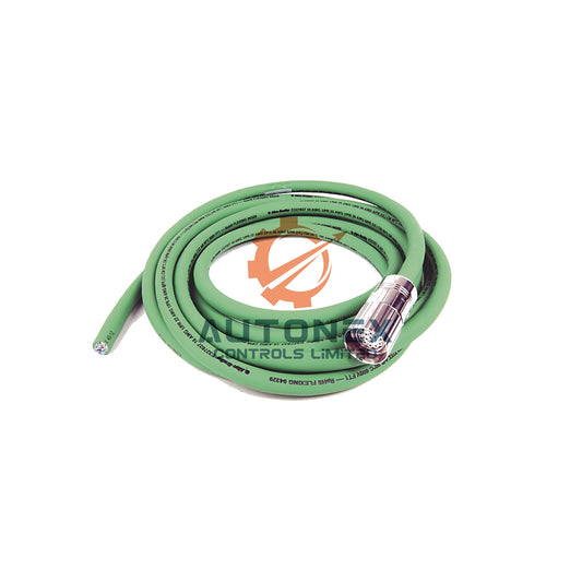
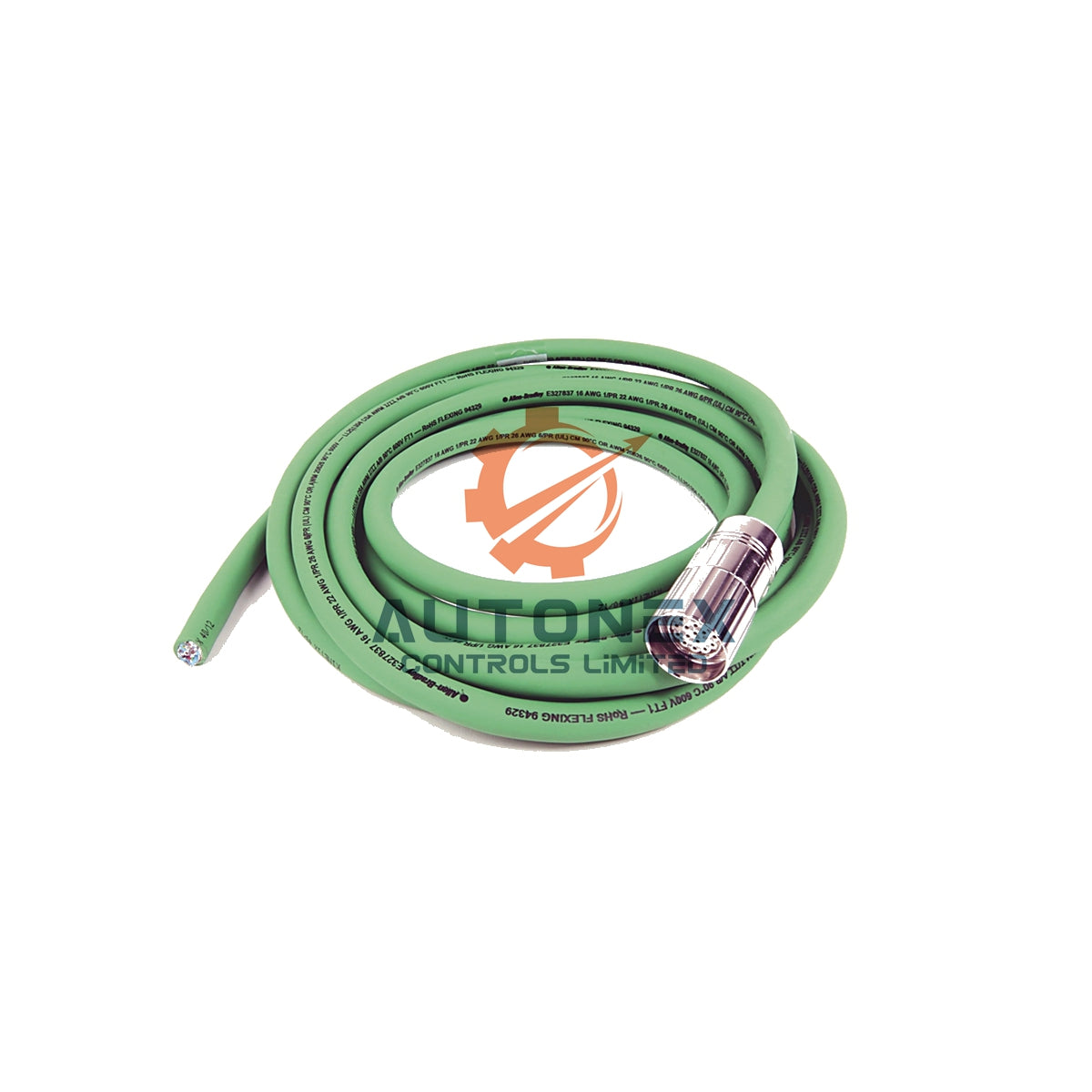
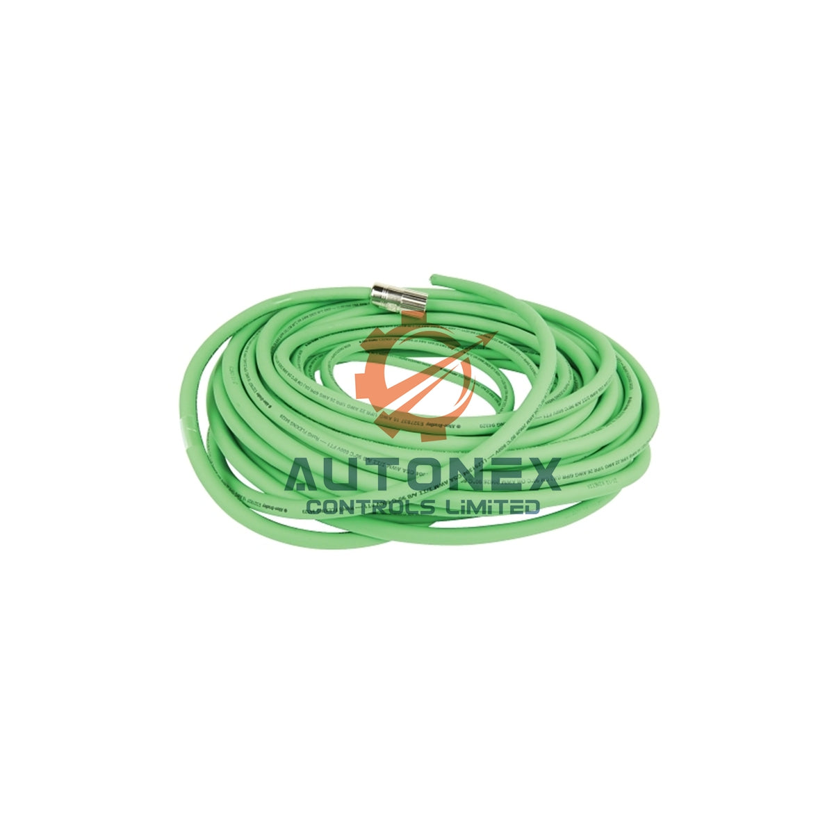
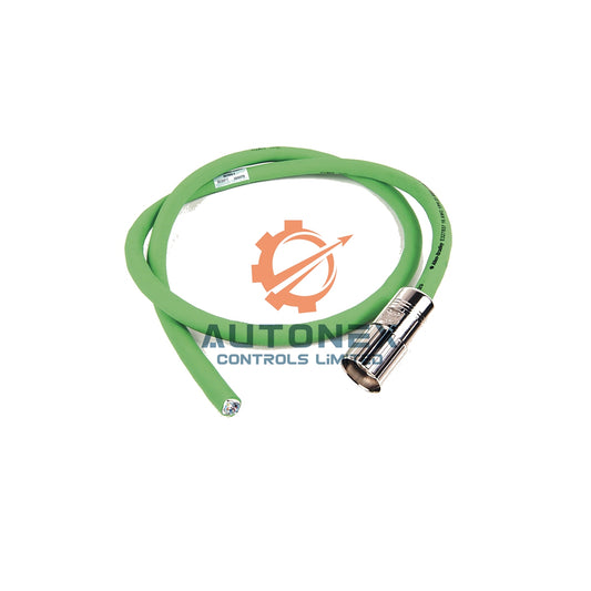
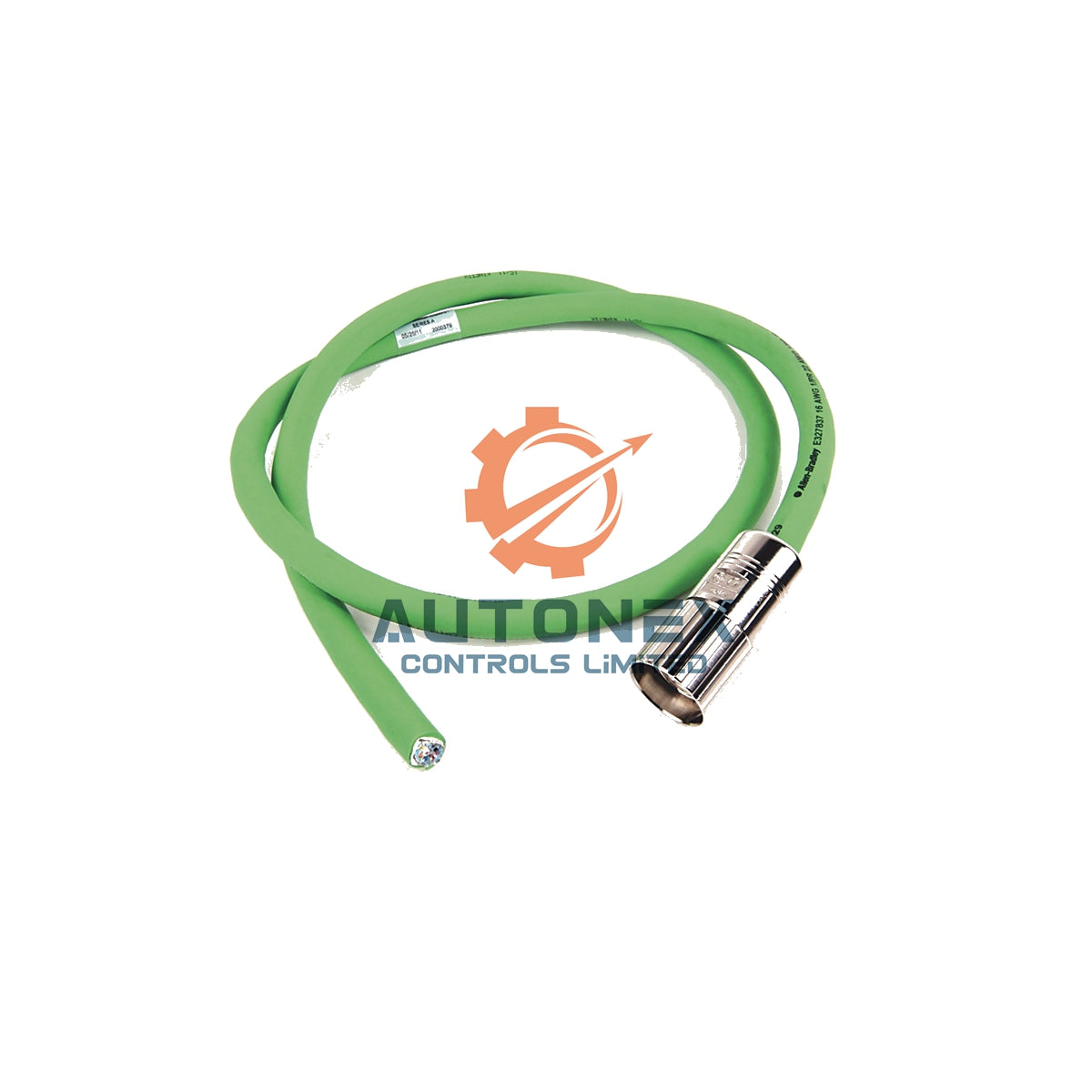
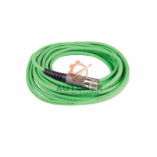
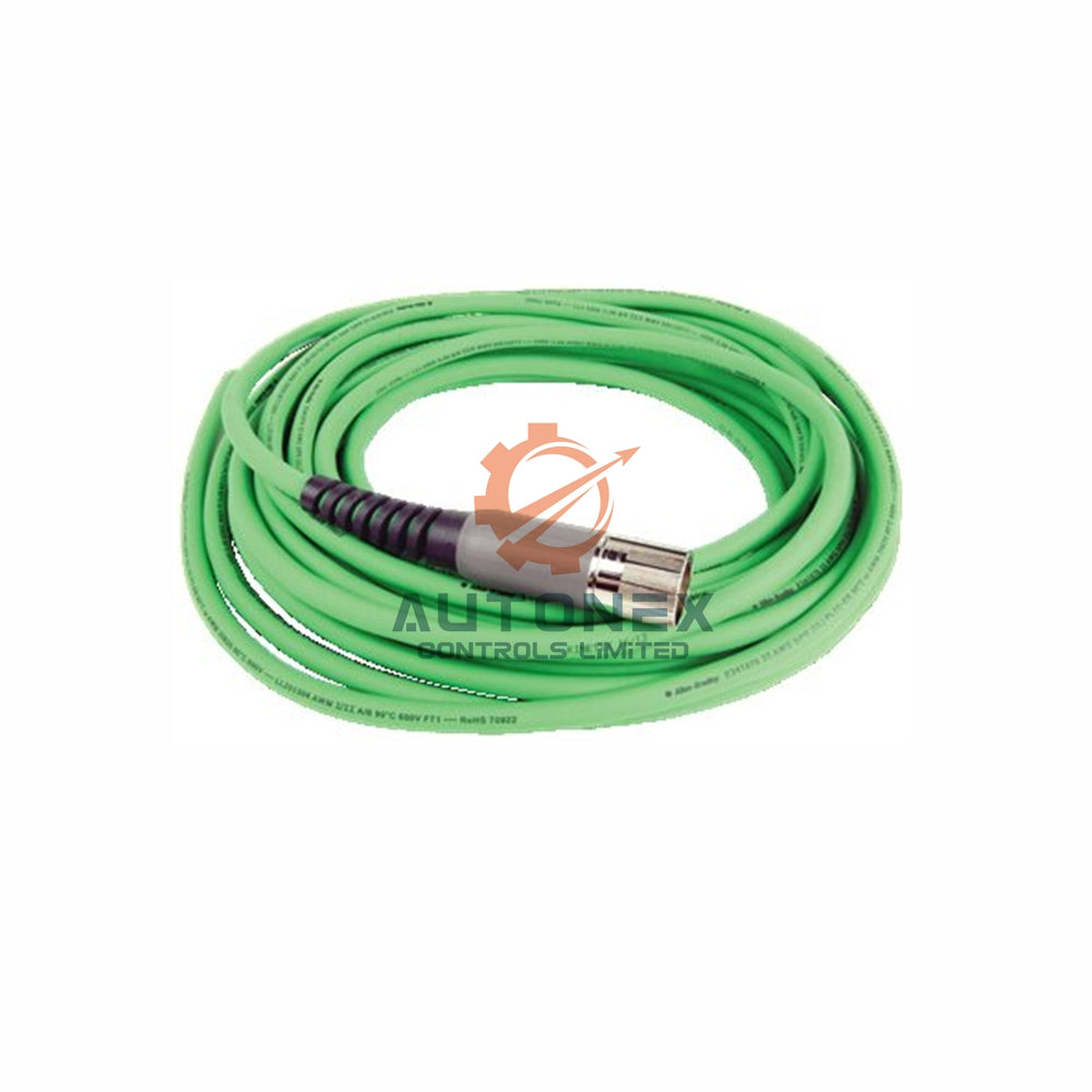
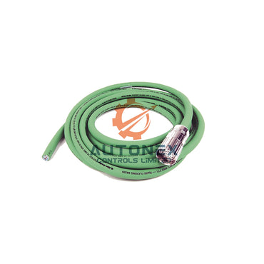
The IC693CBL327 and IC693CBL328 cables connect GE Fanuc Series 90-30 PLC systems. One end has a right-angle 24-pin Fujitsu connector. The other end has stripped leads. The right-angle design saves space in front of the PLC module. It needs only 2 inches of depth. Each cable holds 12 twisted pairs with #24 AWG conductors. Each conductor carries 1.2 amperes. These ratings apply to static conditions. However, continuous flexing changes the game completely.
Why Drag Chains Speed Up Cable Damage
Drag chains force cables to bend, flex, and pull constantly. Research on flexible cables with intermittent faults shows a clear pattern. Conductor strands break one by one under repeated flexing. Cable resistance stays stable until all strands break. Then resistance jumps by more than 40 times. This sudden change marks the critical failure point. In high-speed systems above 1.5 m/s, cables may see over 10,000 bending cycles per day. As a result, fatigue builds quickly in both connector terminations and conductor strands.

Connector Head Failure Modes in Flexing Applications
Connector termination points concentrate stress in drag chain systems. Vibration and repeated motion loosen connector backshells. This creates intermittent open circuits. The crimped area near the connector suffers stress concentration. That stress can break conductors or interrupt the shield. In addition, contact fretting occurs when worn spring sockets lose retention force. A loose male pin shows up in insertion force testing. These connector-side failures often cause random I/O loss without timeout faults. Network fault suppression may hide the real issue.
Conductor Strand Failure Under Continuous Flexing
Conductor strands inside the cable body also fatigue over time. Scanning electron microscope analysis reveals arcing traces and welding at broken strand interfaces. Interestingly, injected currents can temporarily "heal" an intermittent cable. They reduce resistance drastically for a short time. This phenomenon explains why intermittent faults often vanish during energized testing. Furthermore, flexing breaks occur mostly in the bending section, fixed end, and connector root areas. The cable may look fine outside while strands break inside. This hidden damage makes fault localization very difficult.
Connector vs. Conductor: Which Fails More Often?
Field failure data shows a clear trend. In properly installed drag chain applications, conductor strand fatigue dominates. Break points cluster in the bending section. Typical fault patterns include local swelling or distortion. However, connector failures become common when installation violates minimum bend radius requirements. Insufficient strain relief at the connector creates tension that damages crimp areas. This distinction matters for diagnostic strategy. If failures cluster at cable ends near connectors, termination issues likely dominate. If failures occur randomly along the flexing path, conductor fatigue is the primary suspect.
Diagnostic Methods for Intermittent Fault Localization
A systematic approach isolates the failure point efficiently. First, perform visual inspection on bending sections, fixed ends, and connector roots. Look for swelling or distortion. Second, conduct continuity testing while manually flexing suspect sections. The beep stops or resistance jumps when the internal conductor breaks. Third, measure resistance changes from pristine to intermittent state. An increase exceeding 40 times indicates complete strand fracture. Finally, for connector evaluation, check pin retention force and backshell tightness. These combined methods distinguish connector-side from conductor-side failures with high confidence.
Preventive Measures to Extend Cable Service Life
Proper installation and maintenance cut failure rates significantly. Maintain bend radius at least 10 times the cable outer diameter for high-flex applications. Keep drag chain fill ratio between 50% and 70% to prevent excessive friction. Provide 10-15% slack at cable ends to relieve tension from connectors. Use strain relief systems designed for continuous flexing environments. In addition, schedule periodic continuity testing during planned maintenance windows. Early detection of resistance instability allows proactive replacement before unplanned downtime occurs.

Recommended Actions for Maintenance Engineers
When intermittent disconnections occur, avoid simply replacing the cable without root cause analysis. First, verify bend radius compliance in the actual installation. Second, inspect both connector terminations for looseness or pin retention degradation. Third, perform flex testing along the cable path while monitoring continuity. If failures concentrate near connectors, improve strain relief and consider re-termination. If conductor fatigue dominates, select cables with finer strand construction and higher flex ratings. Documenting failure locations across multiple incidents builds statistical evidence for optimal corrective action.
Application Case: Reducing Downtime in a Factory Automation Line
A factory automation line using GE Fanuc Series 90-30 PLCs suffered random I/O dropouts. The maintenance team replaced cables repeatedly without success. Flex testing revealed conductor strand fatigue in the bending section. The team switched to a high-flex cable with finer strands and corrected the bend radius. They also added proper strain relief at the connector. As a result, unplanned downtime dropped by over 60% in the next six months. This case shows why root cause analysis matters more than simple replacement.
Solution Scenario: Combining PLC and DCS Diagnostics
In hybrid control systems, PLC and DCS networks often share cable pathways. A drag chain failure in one cable can trigger alarms across both systems. Engineers should therefore monitor resistance trends and flex cycles together. Modern control systems can log intermittent faults with timestamps. This data helps correlate cable movement with I/O loss. For critical lines, consider continuous flex monitoring with smart cable sensors. This approach supports predictive maintenance and reduces unexpected stoppages in factory automation.
Frequently Asked Questions
1. Why does the IC693CBL327/328 cable fail intermittently in drag chains?
The cable fails because continuous flexing breaks conductor strands and loosens connector terminations. Resistance stays stable until all strands break, then jumps sharply. This creates intermittent open circuits and random I/O loss.
2. How can I tell if the connector head or the conductor strands are failing?
Check failure locations. If failures cluster near cable ends, connector termination issues likely dominate. If failures occur randomly along the flexing path, conductor fatigue is the primary suspect. Flex testing and resistance measurements confirm the cause.
3. What resistance change indicates a complete conductor strand fracture?
A resistance increase exceeding 40 times the pristine value indicates complete strand fracture. Partial breaks may show smaller jumps or unstable readings during flexing.
4. What bend radius should I use for high-flex PLC cables?
Maintain a bend radius at least 10 times the cable outer diameter. This reduces stress on conductor strands and connector terminations in continuous flexing applications.
5. Can injected current temporarily fix an intermittent cable?
Yes. Injected currents can temporarily "heal" an intermittent cable by reducing resistance drastically. This phenomenon explains why intermittent faults often disappear during energized testing. However, the fix is temporary and the cable will fail again.
Contact Information
For inquiries, contact us at sales@nex-auto.com or +86 153 9242 9628.
Partner NexAuto Technology Limited: https://www.nex-auto.com/
Check below popular items for more information in AutoNex Controls
