






IC693CBK003 Expansion Kit Termination Guide: Why Missing Terminators Disrupt PLC Bus Communications
In industrial automation, reliable data exchange between a PLC and its expansion racks depends on many small but critical details. One often overlooked detail is proper bus termination. The IC693CBK003 cable kit for the GE Fanuc Series 90-30 system does not include a terminator plug. Therefore, engineers must install a separate IC693ACC307 terminator at the final baseplate. Without it, signal reflections corrupt data and cause intermittent faults. This article explains the science behind the failure, practical troubleshooting steps, and best practices for factory automation maintenance.
Understanding the Role of the IC693CBK003 Cable Kit in PLC Systems
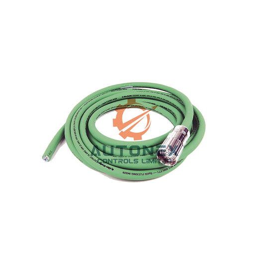
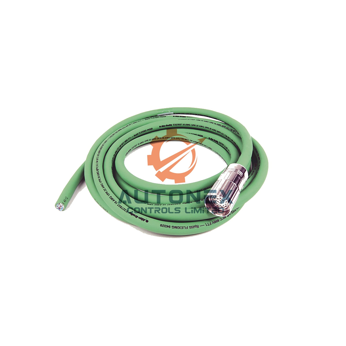
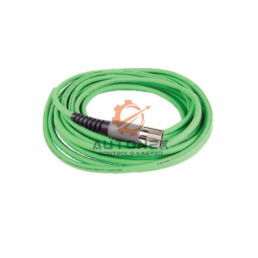
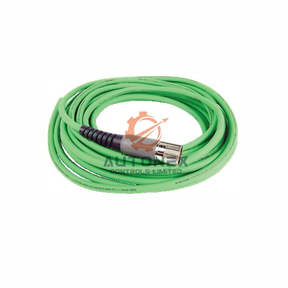
The IC693CBK003 kit contains two 2-meter cables for TBQC connections. It serves the Series 90-30 PLC platform. However, this kit does not provide bus termination. A separate IC693ACC307 plug handles that function. The terminator plug contains a resistor pack inside a 25-pin connector. It installs on the open connector of the last expansion baseplate. This baseplate sits farthest from the CPU in the daisy chain. Without this plug, the I/O bus remains unterminated. As a result, signal reflections occur along the bus wiring.
Why Bus Termination Matters in Industrial Automation Networks
The Series 90-30 I/O expansion bus requires termination at its physical end. Each signal pair needs a 120-ohm, quarter-watt resistor. These resistors connect between specific pin pairs on the connector. The designated pin pairs include 16-17, 24-25, 20-21, 12-13, 8-9, and 2-3. The IC693ACC307 terminator provides exactly this resistive load. Without it, the bus impedance mismatches at the cable end. Consequently, digital signals reflect backward toward the source. This reflection creates high-frequency noise on the network. The reflected waves collide with incoming signals and cause data corruption.

Signal Reflection Physics Behind Bus Failures in Control Systems
Digital signals travel along the bus as electromagnetic waves. When these waves reach an unterminated cable end, they reflect backward. This reflection creates high-frequency noise on the network. The reflected waves collide with incoming signals and cause data corruption. The Series 90-30 bus operates with specific impedance characteristics. The 120-ohm termination matches the characteristic impedance of the bus cable. Without this matching load, energy cannot dissipate properly at the line end. Consequently, the reflected energy interferes with legitimate data frames. The resulting error rate depends on cable length, baud rate, and environmental noise.
Observable Symptoms of Missing Termination in Factory Automation
Operators may notice sporadic communication faults on expansion racks. The CPU may report intermittent I/O module failures. These failures often appear non-reproducible during initial troubleshooting. The system might operate normally for hours, then suddenly drop an expansion rack. Bus activity LEDs may flicker erratically instead of showing steady operation. Station loss occurs without consistent patterns. Higher temperatures tend to worsen these symptoms. As cable length increases, the reflection problem becomes more severe. A 15-meter expansion cable creates more pronounced effects than a 2-meter link.
Genius Bus Protocol and Termination Requirements at Higher Baud Rates
The Genius bus protocol requires termination for reliable operation. At higher baud rates like 76.8 Kbaud, an unterminated bus may fail to power up correctly. The system simply will not initialize without proper termination at that speed. Lower speeds might allow partial operation, but with elevated error rates. Therefore, technicians should always verify termination before adjusting baud rate settings.
Quantifying the Impact of Poor Termination on System Reliability
Signal reflections increase the bit error rate on the bus. The exact degradation depends on several numerical factors. Cable length directly correlates with reflection magnitude. A 50-foot (15-meter) cable exhibits stronger reflections than a 6-foot (2-meter) cable. Baud rate amplifies the problem. Higher frequencies experience more pronounced reflection effects. At 76.8 Kbaud, the system may not even start. At lower rates, intermittent errors persist. The bus impedance mismatch creates standing waves at specific frequencies. These standing waves reduce the noise margin for all connected devices. Moreover, the number of expansion racks influences severity. Each additional rack adds cable length and connector impedance discontinuities. A system with three expansion racks suffers more than one with a single rack. The cumulative reflections compound at each unterminated junction.
Diagnostic Indicators and Troubleshooting Approach for PLC Technicians
Engineers should first verify physical termination at the last baseplate. Look for the IC693ACC307 plug on the open 25-pin connector. If absent, the bus lacks proper termination. The plug weighs approximately 0.05 kg and measures 5 by 2 by 5 centimeters. Next, measure bus resistance with a multimeter. Properly terminated systems show approximately 120 ohms across specific pin pairs. An unterminated bus reads open circuit or very high resistance. These measurements confirm the termination status definitively. The resistor pack inside the terminator plug provides a measurable load. In addition, check the bus activity LED on communication modules. Erratic flickering indicates reflection problems. Steady illumination suggests proper operation. The Genius Bus Controller provides these diagnostic indicators. However, the absence of an LED fault does not guarantee proper termination. Some reflection issues remain invisible until data errors accumulate.
Alternative Termination Methods for Special Cases in DCS and PLC Systems
A 50-foot (15-meter) expansion cable, IC693CBL302, includes built-in termination resistors. When using this specific cable for a single expansion rack, the separate terminator plug becomes unnecessary. The resistors reside inside the cable connector at the expansion baseplate end. Custom-built cables can also incorporate termination resistors. This approach suits specialized installations with unique length requirements. However, standard IC693CBK003 cable kits do not include this feature. Engineers must add termination separately when using these kits. The unused IC693ACC307 plugs shipped with each baseplate serve this purpose. Only the final baseplate in the chain requires termination. Intermediate baseplates must remain unterminated. Installing terminators on middle racks creates double termination and degrades signal quality. The daisy-chain topology demands termination at both physical ends only. The CPU end typically has its own termination internally.

Consequences for System Availability and Maintenance in Industrial Automation
Intermittent faults increase maintenance costs significantly. Technicians spend hours chasing phantom module failures. Production downtime accumulates from repeated stoppages. The root cause remains hidden without proper termination knowledge. Data corruption on the expansion bus can produce incorrect I/O states. Outputs may toggle unexpectedly. Inputs may read false values. These errors create safety concerns in critical control applications. The unpredictable nature of reflection-induced faults makes them particularly dangerous. System availability decreases as error rates rise. The mean time between failures (MTBF) drops dramatically. A properly terminated bus operates reliably for years. An unterminated bus may experience daily or weekly disruptions. The cost of a single IC693ACC307 terminator plug, approximately $147 USD, represents minimal expense compared to downtime losses.
Best Practices for Bus Termination in Series 90-30 Systems
Always install the IC693ACC307 terminator on the last expansion baseplate. Verify the installation during commissioning and after any rack additions. Document the termination status in maintenance records. Include termination checks in routine preventive maintenance schedules. Inspect terminator plugs periodically for corrosion or physical damage. The connector pins must maintain good electrical contact. A loose or corroded terminator provides inadequate termination. Replace damaged plugs immediately. Keep spare terminators in inventory since each baseplate ships with one. When troubleshooting intermittent bus faults, check termination before replacing modules. The terminator plug represents the simplest and cheapest potential solution. Ruling out termination issues early saves diagnostic time. Proper termination ensures the I/O expansion bus delivers reliable performance across all connected racks.
Application Case: Reducing Downtime in a Packaging Line
A food packaging plant experienced random stoppages on its Series 90-30 PLC system. The CPU frequently lost communication with a third expansion rack. Maintenance replaced the rack’s I/O modules twice without success. A controls engineer then measured bus resistance and found an open circuit. The IC693ACC307 terminator was missing from the final baseplate. After installing the plug, the faults disappeared. The plant saved thousands of dollars in lost production. This case shows why termination checks belong in every troubleshooting procedure.
Frequently Asked Questions (FAQ)
Q1: What happens if I do not install the IC693ACC307 terminator?
A1: The I/O bus remains unterminated. Signal reflections corrupt data transmissions. You may see intermittent faults, dropped racks, or erratic LED behavior.
Q2: Can I use any 120-ohm resistor instead of the IC693ACC307 plug?
A2: The IC693ACC307 contains a specific resistor pack for six pin pairs. A generic resistor will not match the connector pinout. Always use the correct terminator plug.
Q3: Where exactly should I install the terminator plug?
A3: Install it on the open 25-pin connector of the last expansion or remote baseplate. This baseplate is farthest from the CPU in the daisy chain.
Q4: Does the IC693CBL302 cable eliminate the need for a terminator?
A4: Yes, but only when used for a single expansion rack. The IC693CBL302 includes built-in termination resistors. Standard IC693CBK003 kits do not.
Q5: How can I quickly test if my bus is properly terminated?
A5: Measure resistance across the specified pin pairs with a multimeter. A properly terminated bus reads approximately 120 ohms. An unterminated bus reads open circuit or very high resistance.
Contact Information
For inquiries, please contact us:
Email: sales@nex-auto.com
WhatsApp: +86 153 9242 9628
Partner NexAuto Technology Limited : https://www.nex-auto.com/
