






Troubleshooting IC693CBK002 Expansion Concentrator: Why Rack 2 Detection Fails in Series 90-30 Systems
Engineers in industrial automation frequently encounter a frustrating scenario. After connecting an IC693CBK002 expansion concentrator interface, Rack 2 remains undetectable. This issue disrupts PLC and DCS control systems on the factory floor. However, the root cause often lies in cable integrity or power supply wiring. This article provides a structured diagnostic methodology. Moreover, it distinguishes between cable failures and PWR331 power deficiencies.
Understanding the IC693CBK002 Role in Expansion Architecture
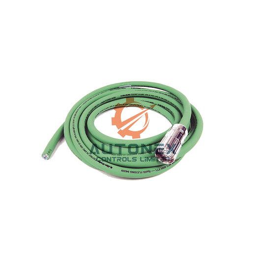
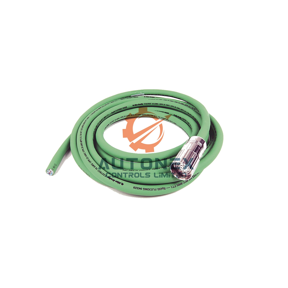
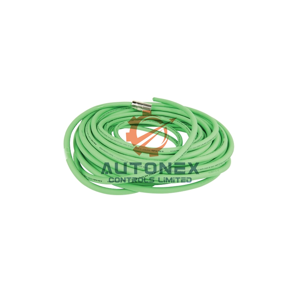
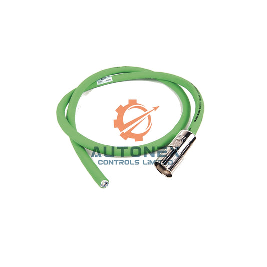
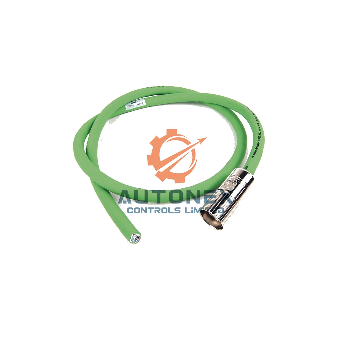
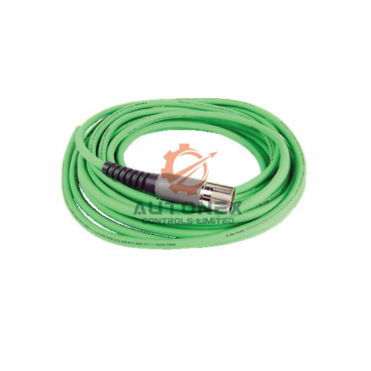
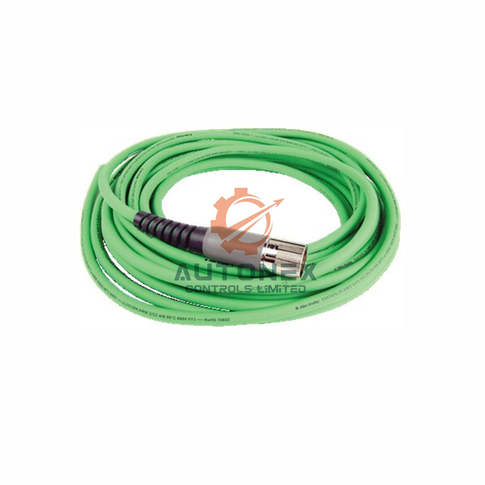
The IC693CBK002 serves as a cable kit for Terminal Block Quick Connect assemblies. This kit includes two critical components. The IC693CBL329 right-side cable and the IC693CBL330 left-side cable form the assembly. Each cable measures roughly 1 meter. Furthermore, 24-pin connectors handle 1.2 Amps per conductor. Consequently, this interface supports high-density 32-point I/O modules. The cables end in stripped wire ends for direct TBQC assembly connection. However, engineers often misidentify this kit as an expansion bus cable. The IC693CBK002 does not carry the backplane expansion bus between racks.
Cable Integrity as Primary Diagnostic Target
Field statistics show cable assemblies cause most communication failures in Series 90-30 systems. The expansion bus runs at data rates up to 153.6 Kbps. It operates over distances up to 15 meters. Signal integrity depends on controlled impedance and proper termination. When Rack 2 stays undetected, the expansion chain between Rack 1 and Rack 2 becomes suspect. A partially open conductor or damaged shield drain wire prevents reliable communication. Therefore, respect the maximum cable length of 50 feet (15 meters) for the entire daisy chain. Exceeding this limit causes unpredictable operation. As a result, continuity testing with a multimeter remains the fastest initial check. Each conductor should show near-zero resistance. The cable jacket should show no signs of pinching or sharp-edge routing. A known-good cable substitution provides definitive confirmation of cable failure.

PWR331 Power Supply Wiring Verification
The PWR331 power supply delivers up to 30 Watts total across three output rails. Its +5 VDC output provides a maximum of 30 Watts for backplane logic. However, the supply requires a minimum of 18 VDC at startup to initiate operation. Once running, it accepts 12 to 30 VDC input. If the PWR331 supply line to Rack 2 remains unconnected, the rack receives no backplane power. Consequently, the expansion receiver module cannot communicate with the CPU. The EXP OK LED on the module should illuminate when backplane 5 VDC power is applied. Absence of this LED provides immediate confirmation of power loss. Field measurements should target the PWR terminal block on Rack 2. Acceptable voltage range for the +5 VDC rail spans 4.90 to 5.25 VDC. Readings below 4.75 VDC under load indicate capacity degradation or wiring resistance. The PWR331 isolates input from backplane at 1500 VAC for one minute. This isolation protects modules but requires proper terminal wiring practices.
Termination and Rack Addressing Requirements
The last expansion rack in any daisy chain requires a terminating resistor. For Series 90-30 expansion, the IC693ACC307 terminator must be installed on the final rack's unused port. Missing termination causes signal reflections that corrupt data at higher baud rates. First and middle racks must not have terminators installed. Rack addressing through DIP switches provides another failure point. Each expansion base uses switches S1 and S2 to set the rack number. Rack 2 typically requires both DIP banks set to ON for the second expansion position. A mismatch between configured and physical rack numbers generates fault code 0x00F8. The CPU monitors DIP switch settings against hardware configuration. When mismatch occurs, the CPU reports an I/O module mismatch fault. However, some CPU modes may bypass this fault reporting. Verifying physical switch positions against the configuration file remains essential.
Structured Diagnostic Methodology and Field Data
A cost-sequenced diagnostic approach minimizes troubleshooting time. First, capture the fault table with timestamps to identify the first failing rack. Second, verify termination and DIP switch positions during a powered-down inspection. Third, measure +5 VDC at each expansion rack under normal load. Data from field incidents reveals that rerouting expansion cables away from VFDs and AC filters resolved noise-induced faults in 24-hour verification tests. Reseating all modules in affected racks addressed oxidized connector issues. The combination of rerouting and reseating eliminated recurring faults in a documented case. When substituting a known-good cable resolves the issue, the original cable contained an internal partial open. This failure mode occurs most often from previous mechanical damage. If cable substitution fails to resolve the problem, power delivery measurements become the next priority.
Distinguishing Between Cable and Power Root Causes
The IC693CBK002 serves TBQC assemblies, not expansion bus communication. If the question specifically concerns this cable kit, the diagnostic focus shifts to terminal block connections. However, Rack 2 detection depends on the expansion bus cables, typically IC693CBL3xx series. For expansion bus faults, the PWR331 supply wiring and the expansion cable both require verification. The PWR331 startup threshold of 18 VDC means marginal supply voltage prevents rack initialization. An unconnected power line produces the same symptom as a severed communication cable. The decisive test involves measuring +5 VDC at Rack 2's power terminals while the CPU attempts rack detection. Present voltage with absent communication indicates a cable fault. Absent voltage confirms a power delivery fault. This single measurement bifurcates the diagnostic path efficiently.

Conclusion and Recommended Verification Sequence
Neither cable failure nor PWR331 wiring deficiency can be assumed without measurement. The IC693CBK002 kit itself rarely causes Rack 2 detection issues in expansion architectures. However, power delivery through PWR331 and expansion bus cable integrity both require systematic verification. A practical sequence begins with fault table capture and DIP switch verification. Continuity testing of expansion cables follows as a low-cost check. Voltage measurement at Rack 2 terminals under load provides the definitive discriminator. A known-good cable substitution confirms cable-related faults conclusively. Missing termination and incorrect DIP settings represent two additional failure modes that mimic cable or power problems.
Application Case and Solution Scenario
Consider a factory automation line running a Series 90-30 PLC with multiple expansion racks. The maintenance team reported intermittent Rack 2 detection failures. They replaced the IC693CBK002 kit twice without success. A systematic check revealed two issues. First, the expansion bus cable between Rack 1 and Rack 2 had a partially open conductor. Second, the PWR331 supply line to Rack 2 showed a loose terminal connection. After repairing the cable and reseating the power terminal, the system ran without faults for six months. This case highlights the importance of verifying both cable integrity and power delivery. In addition, it shows that the IC693CBK002 kit itself rarely causes the problem.
Frequently Asked Questions
Q1: What is the primary function of the IC693CBK002?
A1: The IC693CBK002 is a cable kit for Terminal Block Quick Connect assemblies. It includes the IC693CBL329 and IC693CBL330 cables. It does not transport the backplane expansion bus between racks.
Q2: Why does Rack 2 remain undetected after connecting the IC693CBK002?
A2: Rack 2 detection depends on expansion bus cables, not the IC693CBK002. Check the IC693CBL3xx series cables and the PWR331 power supply wiring. A partial open conductor or missing power causes this symptom.
Q3: What voltage should I measure at Rack 2's power terminals?
A3: Measure +5 VDC at the PWR terminal block. Acceptable range is 4.90 to 5.25 VDC. Readings below 4.75 VDC under load indicate degradation or wiring resistance.
Q4: How do I know if the problem is cable or power related?
A4: Measure +5 VDC at Rack 2 while the CPU attempts rack detection. Present voltage with absent communication indicates a cable fault. Absent voltage confirms a power delivery fault.
Q5: What is the maximum cable length for the expansion bus?
A5: The maximum cable length is 50 feet (15 meters) for the entire daisy chain. Exceeding this limit causes unpredictable operation and communication failures.
Contact Information
For inquiries, please contact us:
Email: sales@nex-auto.com
WhatsApp: +86 153 9242 9628
Partner NexAuto Technology Limited: https://www.nex-auto.com/
Check below popular items for more information in AutoNex Controls

