




GE Series 90-30 Expansion Guide: Baseplates, Cables, and Termination
In industrial automation, reliable I/O expansion is critical for PLC and DCS architectures. The GE Series 90-30 platform remains a trusted choice in factory automation. This guide explains its expansion baseplates, Wye cables, and termination rules. Moreover, it offers practical wiring insights and compatibility notes.
IC693CHS398: The 5-Slot Expansion Baseplate
The IC693CHS398 acts as a 5-slot expansion baseplate for the GE Series 90-30 system. However, this unit lacks an embedded CPU. Therefore, it depends on a host controller for operation. In addition, a 25-pin female D-type connector sits on the right side. This port enables daisy-chain connections to other modules.
Role of the Host Controller in PLC Systems
Host controllers manage data flow across the I/O bus. As a result, the expansion baseplate cannot function alone. This design suits distributed control systems (DCS) and large factory automation setups.
IC693CBL312 and IC693CBL313: Wye Cable Functions
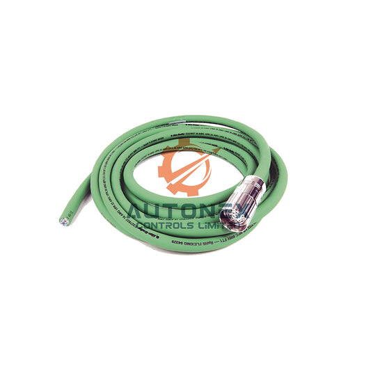
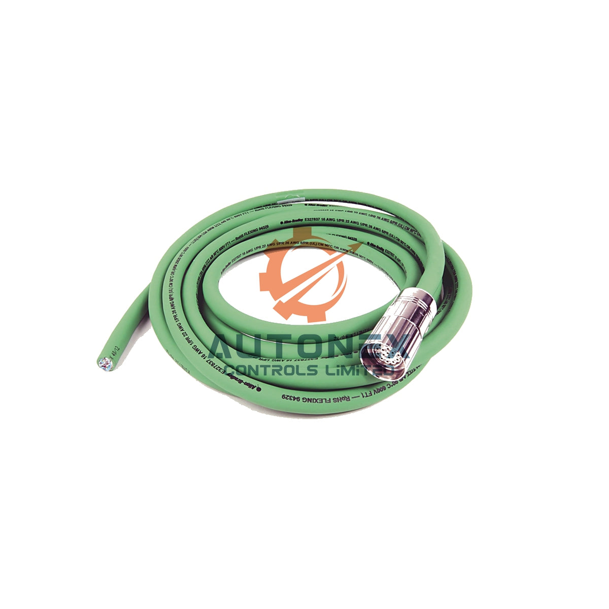
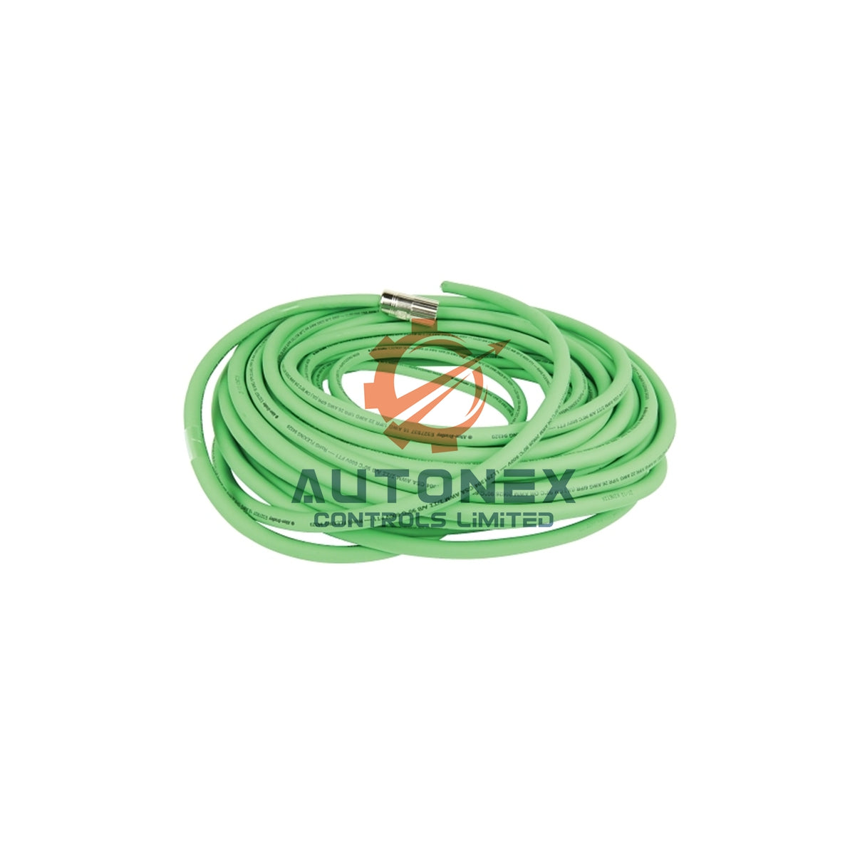
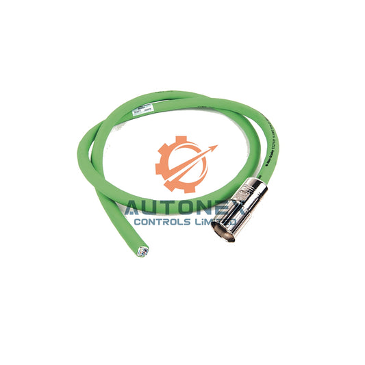
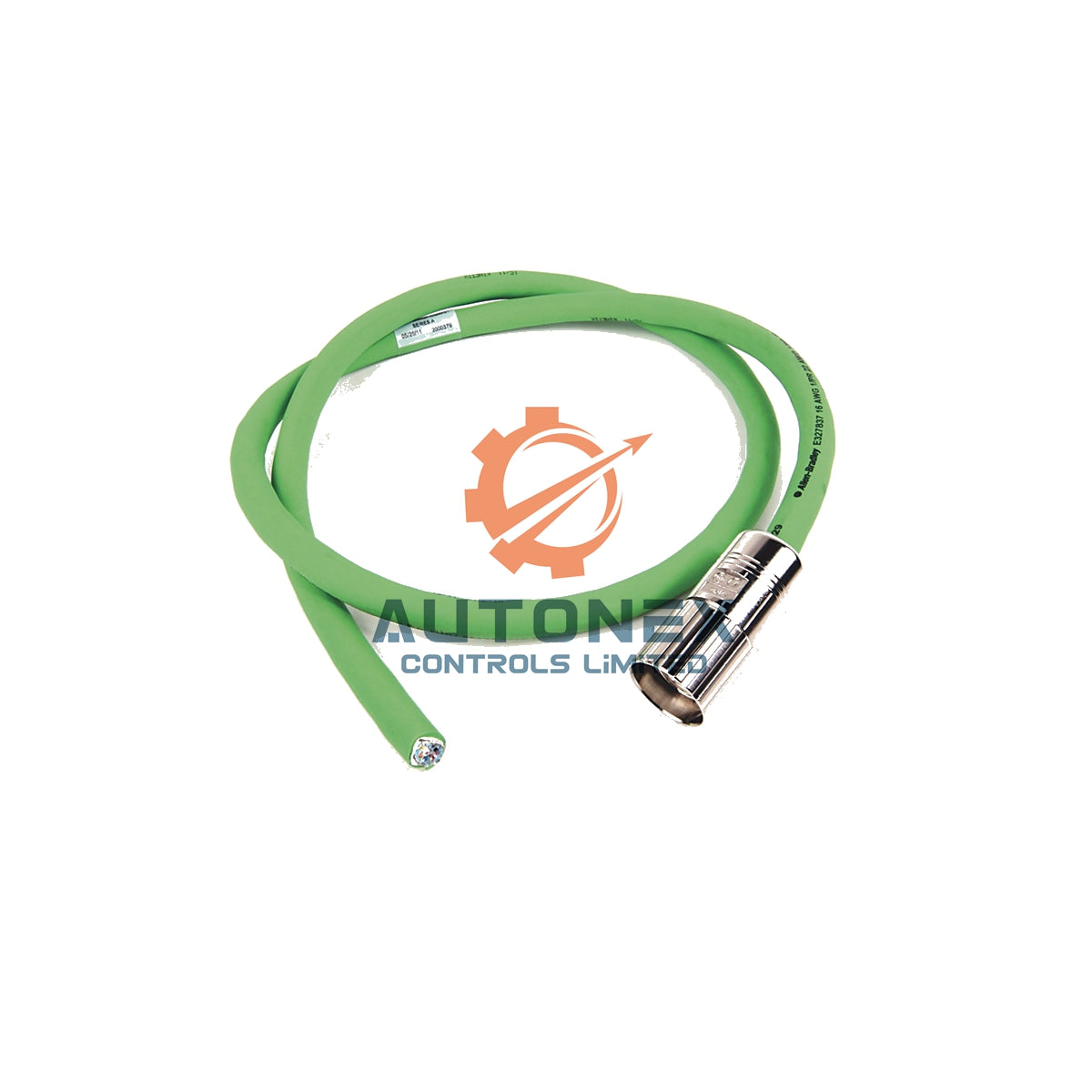
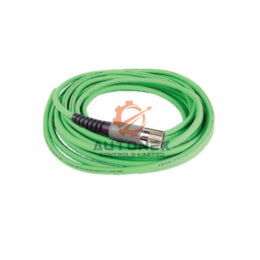
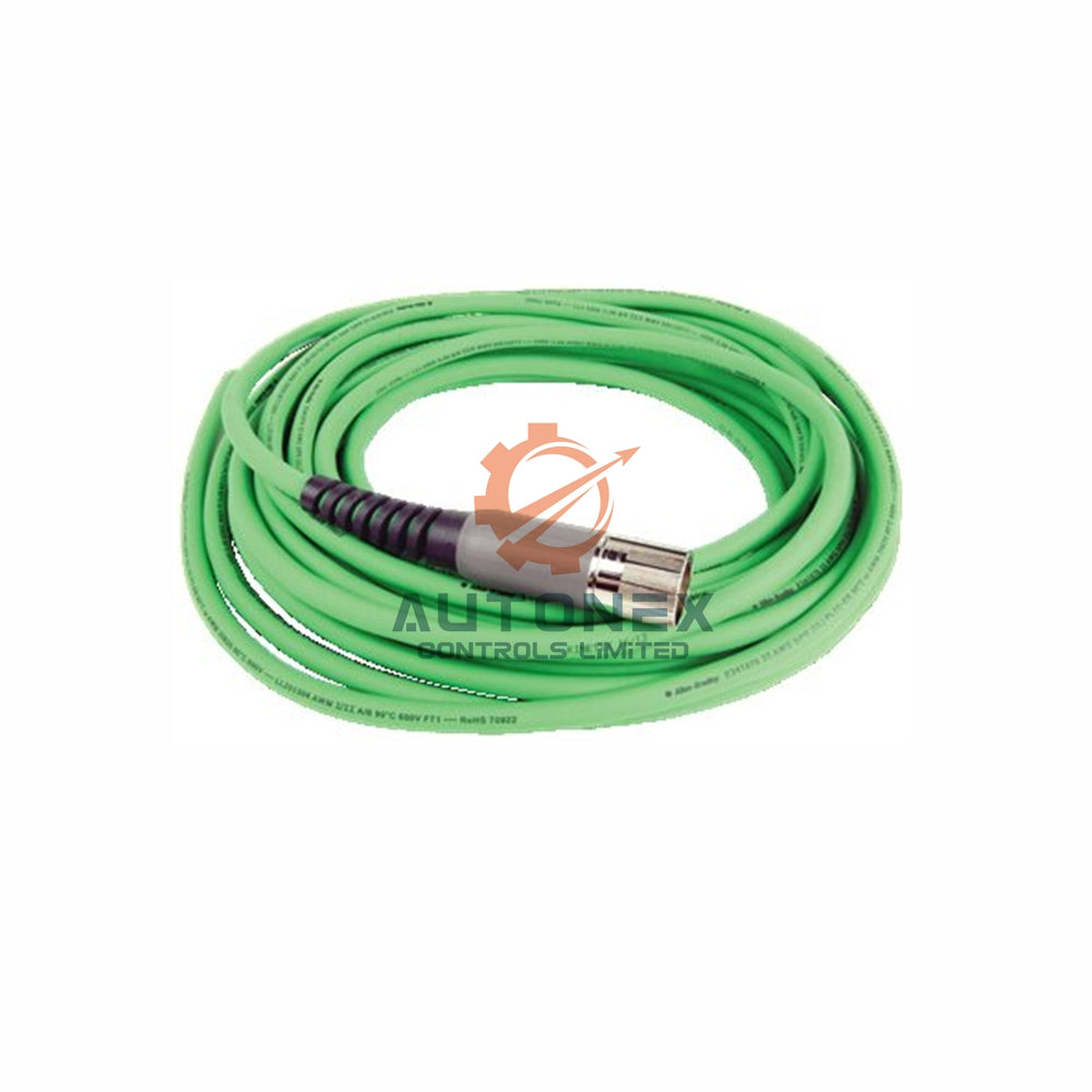
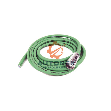
GE offers two Wye cable options for Series 90-30 expansion. The IC693CBL312 provides a short length of 0.15 meters. In contrast, the IC693CBL313 extends to 8 meters. Both cables feature a 25-pin male connector and a dual-head connector. Furthermore, the dual-head end includes one male plug and one female plug.
Why Cable Length Matters in Control Systems
Short cables reduce signal degradation in dense cabinets. However, long cables simplify routing between distant racks. Engineers must balance layout needs against distance limits.

Daisy-Chain Connection Sequence for Series 90-30
The connection order follows a strict daisy-chain pattern. First, attach the single male connector to the CPU baseplate. Then, connect the dual-head male connector to the first expansion baseplate. Next, link the dual-head female connector to the next cable. This sequence continues until the final baseplate receives termination. Therefore, do not skip or reverse any step.
Practical Experience with Daisy-Chain Wiring
Field technicians often label each cable end before installation. This practice prevents miswiring in multi-rack PLC systems. Moreover, it speeds up troubleshooting during factory automation commissioning.
IC693ACC307 Terminator Plug and Bus Termination
The I/O bus requires proper termination at the physical bus end. The IC693ACC307 terminator plug fulfills this need when no further baseplate connects. This plug contains 120-ohm resistors that match the bus impedance. Omitting this termination causes signal reflections and erratic system behavior. As a result, always install the terminator on the last baseplate.
Industry Standard for Termination in DCS and PLC Buses
Proper termination is a fundamental rule in industrial automation. It ensures data integrity across the I/O bus. Neglecting it leads to intermittent faults that are hard to diagnose.
Cable Length Restrictions and Total Distance Limits
Engineers must observe a maximum total cable distance of 15 meters. This limit applies from the CPU to the last expansion baseplate. The IC693CBL313 contributes 8 meters to this total. Mixing both cable types still requires adherence to the 15-meter ceiling. Exceeding this distance threatens data integrity and system timing.
How to Plan Cable Runs for Factory Automation
Map the physical layout before buying cables. Use short IC693CBL312 cables for adjacent racks. Reserve IC693CBL313 cables for longer runs. However, never exceed the total 15-meter limit. This approach avoids signal loss and timing errors.
Wiring Data and Compatibility Notes
The cables carry 28 AWG wire with full shielding. Continuous shielding connects to the metal connector shell around 100 percent of the perimeter. This design provides low-impedance noise dissipation. CPU models 331, 340, and 341 support up to 4 expansion racks. In contrast, CPUs 350 and above support a maximum of 7 racks.
Shielding Best Practices for Noisy Industrial Environments
Full shielding protects signals from electromagnetic interference (EMI). Therefore, verify shield continuity during installation. A broken shield can introduce noise into the control system.
Industrial Application Considerations and Grounding
Potential differences between chassis can disrupt signal transmission. Therefore, all local chassis must reference the same ground point. This practice ensures reliable data communication across the I/O bus. Moreover, it prevents ground loops that damage sensitive electronics.
Grounding Advice from Field Experience
Use a single-point ground bus for all chassis. Check ground resistance periodically. In addition, avoid mixing ground wires with high-power cables. These steps improve reliability in factory automation.

Application Case and Solution Scenario
A packaging line used a Series 90-30 CPU 350 with three expansion racks. The team used one IC693CBL313 and two IC693CBL312 cables. They installed an IC693ACC307 terminator on the last baseplate. As a result, the system ran without signal faults for over two years. This case shows the value of strict daisy-chain and termination rules.
Frequently Asked Questions (FAQ)
What is the IC693CHS398 used for?
It is a 5-slot expansion baseplate for the GE Series 90-30 platform. It requires a host controller because it has no embedded CPU.
Can I mix IC693CBL312 and IC693CBL313 cables?
Yes, you can mix them. However, the total cable distance from CPU to last baseplate must not exceed 15 meters.
Why is the IC693ACC307 terminator plug necessary?
It provides 120-ohm termination at the bus end. Without it, signal reflections cause erratic system behavior.
Which CPUs support 7 expansion racks?
CPU models 350 and above support up to 7 expansion racks. In contrast, CPUs 331, 340, and 341 support up to 4 racks.
How should I ground multiple chassis?
Reference all local chassis to the same ground point. This practice prevents potential differences and ensures reliable data communication.
Contact Information
For inquiries, please contact us:
Email: sales@nex-auto.com
WhatsApp: +86 153 9242 9628
Partner NexAuto Technology Limited : https://www.nex-auto.com/
Check below popular items for more information in AutoNex Controls
