










IC693CPU366 Redundancy Interface Loss of Synchronization: Why Two CPUs Fail Bumpless Switchover
Understanding the Loss of Synchronization Fault
What the IC693CPU366 Redundancy Fault Means for Control Systems
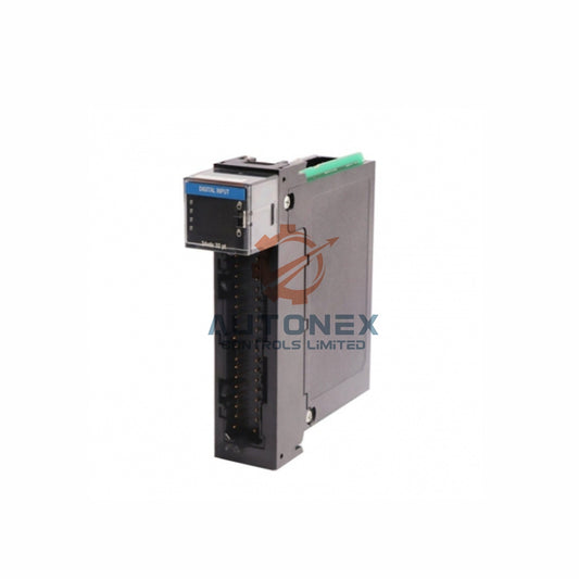
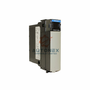
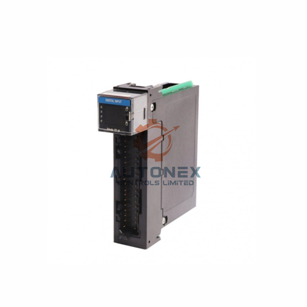
The IC693CPU366 is a legacy CPU module for the GE Fanuc Series 90-30 platform. It offers 240 kB of user memory and executes Boolean logic at 0.22 ms per kilobyte. System architects historically used these CPUs in hot-standby redundant pairs for critical process control. However, the Loss of Synchronization fault often disrupts this redundancy scheme. This error means the primary and standby CPUs no longer share identical process state information. Without synchronized data tables, a switchover event causes process disruption rather than seamless transfer.
Therefore, engineers must treat this fault as a critical availability threat. The redundant architecture depends entirely on continuous data mirroring between both processors. When synchronization degrades, the standby CPU cannot assume control without a measurable process bump. This article identifies the specific failure modes responsible for this condition.
Hardware Link Degradation Between Redundant CPUs
Synchronization Cable and Genius Bus Issues in PLC Redundancy
The synchronization channel between redundant CPUs relies on dedicated communication hardware. Many 90-30 hot-standby configurations use Genius bus communication or a proprietary synchronization cable. Physical degradation of this link directly causes Loss of Synchronization errors. For instance, loose cable terminations introduce intermittent connectivity. Similarly, electromagnetic interference from nearby variable frequency drives can corrupt synchronization packets.
Furthermore, the synchronization link requires proper termination resistance. Missing or incorrect termination resistors cause signal reflections. These reflections corrupt data frames and trigger synchronization timeout faults. Engineers should measure link continuity and verify termination values against the original installation documentation. Cable routing changes near high-voltage conductors represent another common source of induced noise.

Firmware Revision Mismatch in CPU Modules
Why Identical Firmware Matters for Bumpless Switchover
The IC693CPU366 received multiple firmware revisions throughout its production lifecycle. The synchronization protocol requires identical firmware versions on both CPUs. A revision mismatch causes the synchronization engine to reject data frames from the partner CPU. As a result, the redundant pair fails to establish a consistent synchronization state.
In addition, firmware upgrades performed on only one CPU create this exact condition. User information including program logic and configuration tables clears automatically during firmware changes. Therefore, engineers must verify that both CPUs report identical firmware revision codes before commissioning the redundant pair. The IC693CPU366 module supports programming through Proficy Machine Edition Logic Developer version 5.0 or later. This software provides a firmware revision query function for both processors.
Scan Time Divergence Between Primary and Standby Units
How Asynchronous Tasks Break CPU Synchronization
Redundant CPUs must execute identical scan cycles to maintain synchronization. The IC693CPU366 achieves a scan rate of 0.22 ms per kilobyte of Boolean logic. However, scan time diverges when the two CPUs experience different I/O update loads. For example, the primary CPU may process additional communication requests from HMI or SCADA systems. These asynchronous tasks extend the primary scan cycle beyond the standby cycle time.
Once scan times diverge beyond the synchronization tolerance window, the CPUs cannot reconcile their data tables. The standby CPU receives synchronization data that references an older or newer scan context. Therefore, the synchronization engine aborts the handshake and reports Loss of Synchronization. Reducing communication overhead on the primary CPU helps maintain aligned scan cycles.
Configuration Errors in Redundancy Parameters
Chksum Wrds, MaxON, and Data Table Boundaries
Proper redundancy operation requires specific configuration parameters within the CPU hardware configuration. The Chksum Wrds parameter, for instance, must be set to 11 for the primary CPU and 12 for the standby CPU in hot-standby applications. Incorrect values in these parameters prevent the synchronization protocol from initializing correctly.
Moreover, the MaxON software manages redundancy data exchange and switchover logic. Incompatible MaxON versions with the installed Proficy Machine Edition release cause configuration failures. Engineers should verify that the redundancy configuration includes all required data tables. Missing reference memory areas within the synchronization scope create partial synchronization states. These partial states eventually collapse into full synchronization loss.

Diagnostic Procedures for Identifying Root Cause
Fault Tables, Oscilloscope Checks, and Application Verification
Systematic diagnosis begins with the fault tables within Proficy Machine Edition. The CPU records synchronization faults with specific error codes that indicate the failure category. Engineers should retrieve these fault tables from both CPUs and compare timestamps. Correlated faults suggest a communication link issue, while asymmetric faults point to configuration or firmware problems.
Subsequently, technicians should measure the physical synchronization link with an oscilloscope. Signal integrity analysis reveals reflections, attenuation, or noise injection. In addition, verifying that both CPUs run identical application programs eliminates program divergence as a cause. The IC693CPU366 supports a maximum of 4096 discrete I/O points and 240 kB of register memory. Applications exceeding these limits may exhibit erratic synchronization behavior.
Best Practices for Maintaining Redundant Synchronization
Preventive Maintenance and Migration to PACSystems RX3i
Preventive maintenance reduces the probability of Loss of Synchronization faults. Engineers should schedule periodic verification of synchronization link integrity. This verification includes cable inspection, termination resistance measurement, and fault table review. Maintaining identical firmware revisions across both CPUs prevents protocol-level incompatibility.
Furthermore, documenting the redundancy configuration creates a baseline for future troubleshooting. The configuration record should include Chksum Wrds values, MaxON version, and synchronized data table boundaries. Finally, considering migration to the PACSystems RX3i platform provides modern redundancy features. The RX3i uses reflective memory technology for tighter CPU synchronization and bumpless switchover capability. This technology eliminates many failure modes present in legacy 90-30 redundancy schemes.
Application Case and Solution Scenario
Real-World Example: Restoring Bumpless Transfer in a Water Treatment Plant
A municipal water treatment plant operated a GE Fanuc Series 90-30 hot-standby pair with IC693CPU366 modules. The standby CPU repeatedly reported Loss of Synchronization during peak demand hours. The maintenance team first checked the synchronization cable and found loose termination screws. After tightening the connections, the fault persisted. A firmware query revealed that the primary CPU ran a newer revision than the standby unit. The team upgraded both CPUs to the same firmware revision and verified the Chksum Wrds settings. They also reduced HMI polling frequency on the primary CPU. As a result, the redundant pair achieved stable bumpless switchover and passed a controlled failover test. This case shows that multiple small issues can combine to break synchronization in industrial automation systems.
For similar challenges, NexAuto Technology Limited supports legacy GE Fanuc and PACSystems platforms. Contact our team for diagnostics, spare parts, and migration planning.
Frequently Asked Questions
What does Loss of Synchronization mean on an IC693CPU366 redundant pair?
It means the primary and standby CPUs no longer share identical process state data. A switchover will therefore cause a process bump instead of a seamless transfer.
Can a firmware mismatch alone cause Loss of Synchronization?
Yes. The synchronization protocol requires identical firmware revisions on both CPUs. A mismatch causes the synchronization engine to reject data frames from the partner CPU.
How do I check synchronization link integrity on a Series 90-30 hot-standby system?
Measure link continuity and termination resistance. Use an oscilloscope to inspect signal integrity for reflections, attenuation, or noise injection.
What are the correct Chksum Wrds values for hot-standby operation?
Set Chksum Wrds to 11 for the primary CPU and 12 for the standby CPU in hot-standby applications.
When should I migrate from Series 90-30 redundancy to PACSystems RX3i?
Consider migration when spare parts become scarce, firmware support ends, or you need tighter synchronization. The RX3i uses reflective memory for bumpless switchover.
Contact Information
Inquiries: sales@nex-auto.com
Phone: +86 153 9242 9628
Partner NexAuto Technology Limited: https://www.nex-auto.com/
Check below popular items for more information in AutoNex Controls
| TC-ODX081 | TC-ODA161 | TC-ODJ161 |
|---|---|---|
| TC-ODX161 | TC-ODD321 | TC-IDJ161 |
| S30A-7111CL | S30A-6011EA | S30A-7011EA |
| S30A-7011BA | S30A-4011BA | S30A-6011GB |
