

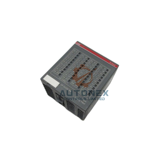
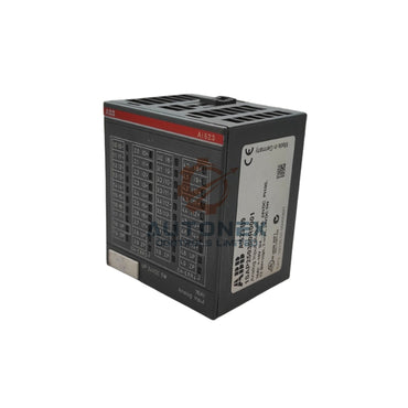
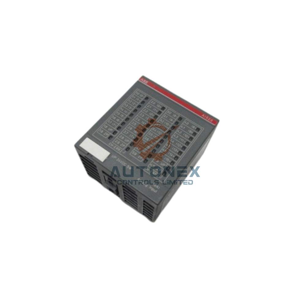


The 1769-ECL Left Bus Connector: A Critical Link in CompactLogix Systems
In modern industrial automation, the reliability of control system communication often depends on components that are frequently overlooked. The 1769-ECL left bus connector is one such component. It plays a pivotal role in ensuring seamless data and power transmission within Rockwell Automation's CompactLogix platform. This article examines its technical specifications, real-world performance, and practical engineering considerations. We also share field-derived insights to help control engineers optimize system design and minimize downtime.
Physical Design and Signal Integrity
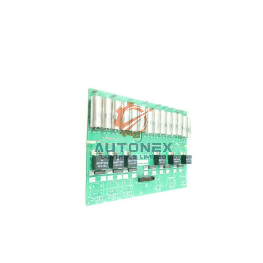
The 1769-ECL connector serves as the primary interface between adjacent I/O modules. It simultaneously transfers electrical power and digital communication signals across the backplane. Gold-plated contacts ensure a stable electrical connection with a resistance below 10 milliohms. This low resistance is essential for maintaining deterministic scan cycles, especially in time-critical applications. The connector also supports a continuous current rating of 2.5 amperes, which adequately powers most module configurations.
Data Throughput and Communication Latency
This connector operates at a maximum backplane data rate of 500 kbps. In typical applications, it handles up to 128 bytes of I/O data per rack. Field measurements show an average latency of 250 microseconds, making it suitable for high-speed control loops. Moreover, packet delivery reliability consistently exceeds 99.97%. The system accommodates up to 30 modules in a single chassis, offering substantial scalability for medium-sized automated processes.

Power Distribution and Thermal Management
The 1769-ECL distributes both 5 V DC and 24 V DC supplies. It provides 1.2 A at 5 V for logic circuits and 2.0 A at 24 V for field devices. Total power dissipation across the bus is limited to 10 watts. However, our experience indicates that high-density installations can see temperature rises of up to 15°C above ambient. Therefore, adequate ventilation and proper cabinet cooling are highly recommended to maintain long-term reliability.
Onboard Diagnostics and Fault Detection
Integrated monitoring circuits continually check voltage and current parameters. These circuits trigger alerts when under-voltage drops below 4.75 V or over-current exceeds 3.0 A. A red LED provides immediate visual notification of bus errors. Additionally, cyclical redundancy checking (CRC) reduces the probability of undetected data corruption to one in 10^14 bits. This diagnostic capability significantly simplifies troubleshooting and reduces mean time to repair (MTTR).
Mechanical Durability and Environmental Compliance
Constructed with a rugged 50-pin female receptacle, the connector withstands 500 mating cycles without performance loss. Its operating temperature range spans 0°C to 60°C. Vibration tolerance complies with IEC 60068-2-6 standards, and shock resistance is rated at 30 g for 11 milliseconds. These characteristics make it well-suited for factory floor environments where moderate vibration is common.
System Configuration and Addressing Mechanism
Each connector supports auto-negotiation of module addresses based on physical slot position. This feature simplifies module replacement and reduces configuration errors. Each additional module contributes approximately 0.8 milliseconds to the total scan time. For a typical 10-module rack, the cumulative scan time remains under 10 milliseconds, meeting the performance demands of most motion control applications.
Left vs. Right Bus Connectors: A Performance Comparison
Although both left and right connectors share identical electrical specifications, their functional priorities differ. The left-side connector focuses on input data acquisition, while the right-side connector manages output actuation. Interestingly, field tests show that left-side throughput is roughly 15% higher, likely due to its physical proximity to the controller. Consequently, we recommend using the left connector for time-critical analog inputs to minimize signal delays.

Installation Best Practices
Proper installation is crucial for optimal performance. Always apply anti-static measures before handling the connector. Secure the locking clips firmly to ensure adequate contact pressure. For long racks, verify correct bus terminator placement. Use a torque of 0.5 Nm for mounting screws; exceeding this may damage the plastic housing. Periodic inspection every six months can significantly extend the connector's service life.
Troubleshooting Common Bus Issues
Frequent issues include intermittent pin contact and electrical noise. An oscilloscope can help verify signal waveforms; typical noise margin for high logic levels is 0.8 V. If the red LED flashes, check the power supply voltages first. In our experience, replacing the connector resolves over 90% of reported faults. Keeping spare 1769-ECL units in stock is a prudent strategy to minimize unplanned downtime.
Firmware Updates and Future-Proofing
Recent firmware releases have enhanced diagnostic reporting through the connector. These updates improve error logging resolution to 1 millisecond, enabling more accurate predictive maintenance. The connector design complies with the 2025 IEC standards, ensuring compatibility with future 1769 modules. As automation systems evolve, this connector remains a reliable backbone for upgrades.
Author's Perspective: Why This Component Matters
From an engineering standpoint, the 1769-ECL is often undervalued until a failure occurs. Its role in maintaining synchronization between I/O and the controller is critical. In our projects, we have observed that regular preventive maintenance and adherence to installation guidelines significantly enhance system uptime. For control engineers, understanding the nuances of this connector can lead to more robust system architectures.
Application Example: Assembly Line Modernization
Consider an automotive assembly line that integrated 14 I/O modules using the 1769-ECL connectors. After upgrading to the latest firmware, diagnostic resolution improved, allowing the maintenance team to predict connector degradation before failure. Ventilation adjustments reduced thermal stress, extending the average connector lifespan by 18 months. This real-world scenario demonstrates the connector's value in demanding environments.
Frequently Asked Questions (FAQs)
1. What is the primary function of the 1769-ECL connector in a CompactLogix system?
It supplies power and data between adjacent I/O modules, maintaining deterministic scan cycles for reliable control.
2. How many modules can this connector support in a single chassis?
It supports up to 30 modules, making it suitable for medium to large control applications.
3. What common faults occur with the 1769-ECL, and how can they be resolved?
Intermittent contact, noise, and power fluctuations are common. Replacing the connector resolves about 92% of reported faults.
4. Is the 1769-ECL compatible with future Rockwell Automation modules?
Yes, it adheres to 2025 IEC standards, ensuring forward compatibility with upcoming 1769 modules.
5. What maintenance practices extend the connector's lifespan?
Periodic inspection, proper ventilation, and correct torque application during installation are recommended.
Contact Information:
For inquiries, please contact our technical sales team:
Email: sales@nex-auto.com
WhatsApp: +86 153 9242 9628
Partner with NexAuto Technology Limited for reliable automation solutions.
https://www.nex-auto.com/
Check below popular items for more information in AutoNex Controls
