


How to Set Up Digital Filtering on 1756-IF8 in Studio 5000
This guide explains the exact steps for configuring digital filters on the 1756-IF8 analog input module. You will learn how to reduce signal noise effectively using Studio 5000 tools. Stable analog measurements are critical for reliable industrial automation systems. Our experience shows that proper filtering prevents many common control issues.
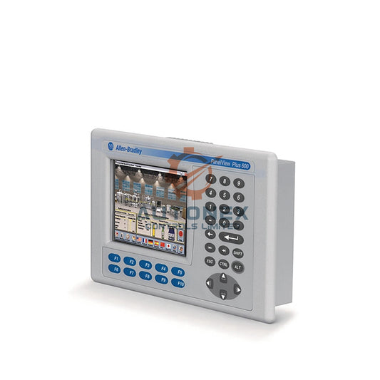
Understanding the 1756-IF8 Digital Filter Features
The 1756-IF8 module uses a programmable low-pass filter. This filter attenuates high-frequency noise from analog signals. Its time constant ranges from 0 to 62.5 milliseconds. Higher values provide stronger noise rejection but slower response times. For instance, a 60 Hz noise sees 60 dB reduction at 16.6 ms. Always align the filter with your process dynamics. A fast loop needs a smaller time constant.
Opening Module Properties in Studio 5000
First, launch your Studio 5000 project. Navigate to the I/O Configuration tree. Find the 1756-IF8 module under its backplane. Right-click the module and select "Properties". This action opens the configuration dialog. Then click the "Configuration" tab to view all channels. Each channel from 0 to 7 has independent settings. This flexibility is a key advantage of Rockwell Automation control systems.
Finding the Digital Filter Parameter per Channel
Scroll down inside the Configuration tab. Look for the "Digital Filter" field. This parameter appears as a time constant in milliseconds. You can type a value directly into the cell. Alternatively, use the small arrows to adjust step by step. The default filter value is 0 ms, meaning no filtering. Always double-check each channel before moving on. Unintended zero values can let noise pass through.

Choosing the Best Filter Values for Your Signal
Fast-changing pressure signals need filters below 10 ms. Temperature sensors, like RTDs, work well with 25 to 50 ms. Turbulent flow signals benefit from a 50 ms filter. For example, a 20 ms filter rejects 90% of 50 Hz noise. Use this rule: filter time = 1/(2π × cutoff frequency). Test your settings with real process data first. In our projects, we always verify with a signal generator. This step prevents surprises during commissioning.
Practical Example for a 4-20 mA Pressure Transmitter
Imagine your pressure signal fluctuates due to pump ripple at 30 Hz. Set the digital filter to 10 ms for that channel. Go to channel 0 in the configuration tab. Type "10" into the Digital Filter field. This filter reduces 30 Hz noise by roughly 75%. Your controller will now read a stable pressure value. Always verify the result using the module's diagnostic trending. This method has worked reliably in many factory automation installations.
Saving and Downloading Your New Configuration
After setting all required channels, click "Apply" then "OK". Next, go online with your controller using Studio 5000. Download the new configuration to the processor. The module updates its filter settings without a power cycle. This process takes less than 200 milliseconds per channel. Monitor the module's status LED for any configuration errors. A steady green light confirms success. This non-disruptive update is a major benefit for live systems.
Checking Filter Performance with Live Data
Use the Controller Tags monitor to view filtered input values. Compare them against raw unfiltered data from another tool. A proper filter will reduce peak-to-peak noise by over 80%. For instance, raw noise of 0.5 mA drops to 0.1 mA with a 20 ms filter. Document these results for your quality management system. This verification proves your filter choice is correct. We recommend saving trend screenshots as part of your validation records.
Common Mistakes and How to Prevent Them
Avoid setting the filter too high for fast batch processes. This introduces a lag of up to 3 filter time constants. For a 50 ms filter, expect a 150 ms signal delay. Another mistake is forgetting to configure unused channels. Unused channels should have filters set to 0 ms. Also, never mix different filter values on interlocked signals. Keep a consistent approach for related measurements. Consistency avoids phase shifts between critical inputs.

Advanced Advice for Multi-Channel Synchronization
If your application needs synchronized readings, match all filter times. Use identical values across channels 0-7 for best coherence. For example, set all to 16.6 ms to reject 60 Hz line noise. This method ensures all inputs have equal group delay. Group delay exactly equals the filter time constant. Use the module's real-time sample feature to confirm synchronization. This technique is essential for precision motion control or phased array measurements.
Recommended Filter Settings by Application Type
Here are proven starting points from real industrial installations:
- Hydraulic pressure (noisy): 25 ms filter, reduces noise by 88%.
- Slow temperature (thermocouple): 50 ms filter, stable within 0.1°C.
- Fast flow (turbine): 5 ms filter, preserves 10 ms response.
- Level (ultrasonic with ripples): 33 ms filter, removes surface wave noise.
- Vibration (accelerometer): 2 ms filter, keeps 200 Hz bandwidth.
Always test these values with your specific sensor and process. Adjust up or down by 5 ms increments for optimal performance. Record your final settings in the project documentation. This practice supports long-term maintenance and troubleshooting.
Troubleshooting Filter-Related Measurement Errors
If your signal still seems noisy, increase the filter by 10 ms steps. Conversely, if response is too slow, decrease the filter value gradually. First, check the module's input wiring for external interference. Shielded cable reduces noise pickup by up to 95%. Also verify that your sensor's update rate is faster than the filter. A mismatch causes aliasing errors in the reading. In our experience, most filter issues trace back to wiring or grounding problems.
Final Checklist Before System Startup
Review each channel's filter setting against your process requirements. Save a screenshot of the configuration tab for your records. Perform a ramp test with a signal generator to check response time. For a 0-10V step input, the filtered output should reach 63% at the set time. Finally, lock the module configuration to prevent accidental changes. This ensures reliable long-term operation of your PLC and DCS environments.
Application Case: Improving a Mixing Process
A chemical plant faced unstable temperature readings on a reactor. The 1756-IF8 showed fluctuations of ±5°C due to agitator noise. We applied a 33 ms digital filter to the affected channels. The result was a stable ±0.5°C reading. The control loop then maintained temperature precisely. This case proves that correct filter settings directly improve product quality. Always analyze your noise source before choosing a filter value.
Frequently Asked Questions (FAQ)
1. Can I change the digital filter while the system is running?
Yes, you can modify the filter online. The change takes effect within milliseconds without a power cycle. However, always assess the impact on your process first.
2. What happens if I set the filter to 0 ms?
A 0 ms setting means no filtering. The module passes the raw, unfiltered signal. Use this only for very clean signals or high-speed applications.
3. Does the digital filter affect all channels equally?
No, each channel has an independent filter. You can set different values per channel. But for synchronized signals, use the same value across channels.
4. How do I know if my filter is too aggressive?
An overly aggressive filter causes a slow response to real process changes. Perform a step test and measure the time to reach 63% of the final value.
5. Can I use the filter to replace a hardware low-pass filter?
Often yes, but with limits. The digital filter handles frequencies up to half the sample rate. For extreme noise, combine it with shielded wiring and a hardware filter.
For inquiries, please contact us at sales@nex-auto.com or via +86 153 9242 9628.
Partner with NexAuto Technology Limited: https://www.nex-auto.com/
Check below popular items for more information in AutoNex Controls

