

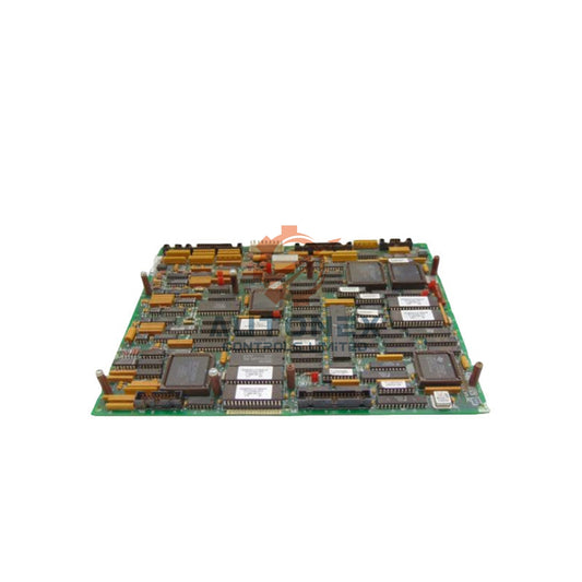
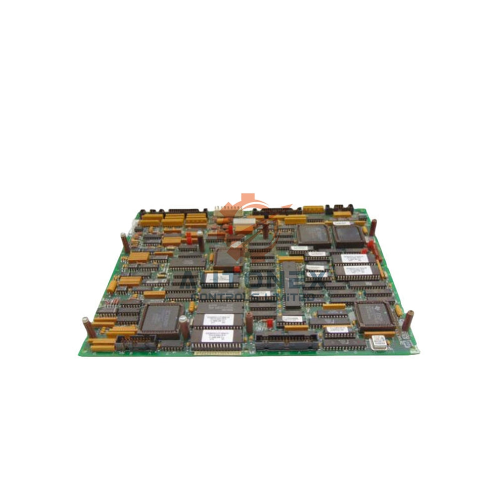
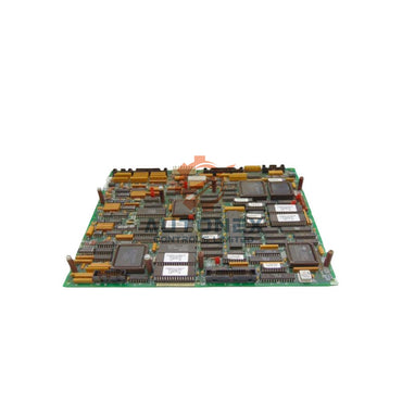
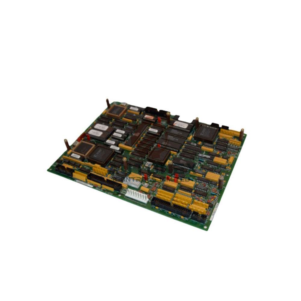
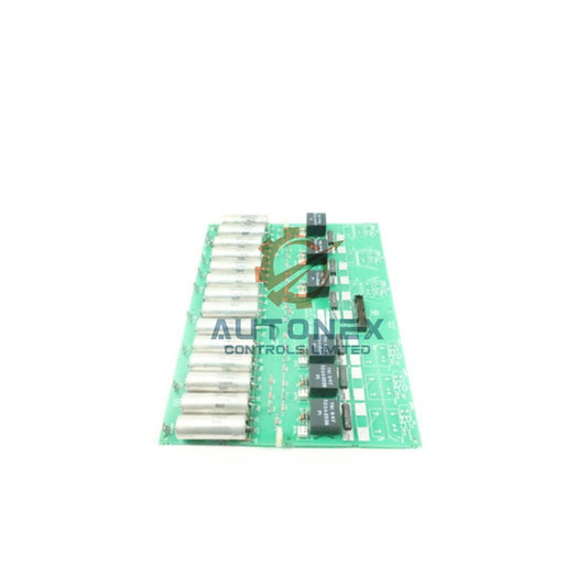
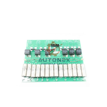
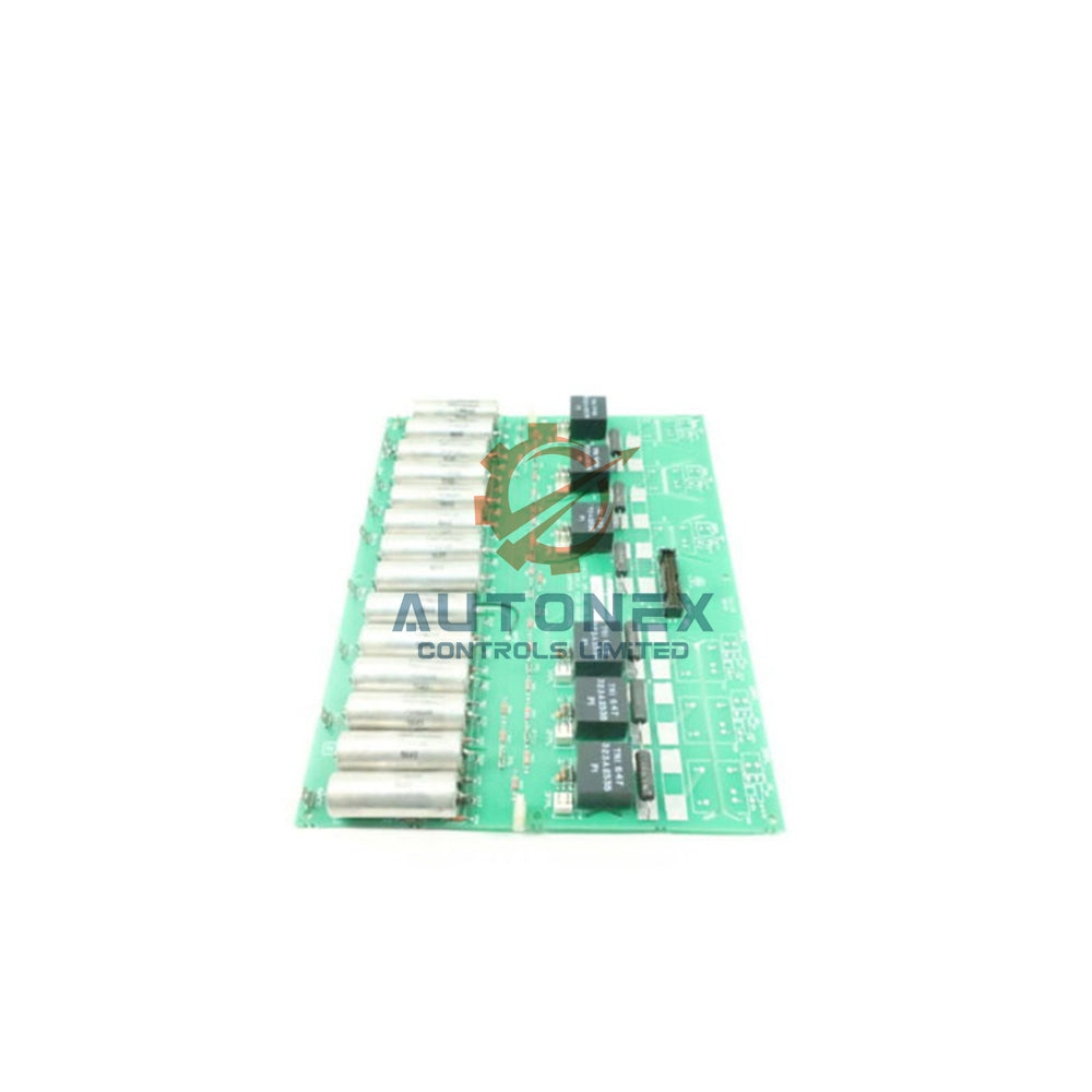

Decoding IC693CPU352 Fault Diagnostics: A Practical Guide to %S and %SR System Bits
Fault diagnostics in the GE Fanuc Series 90-30 CPU 352 rely on a well-defined architecture of system bits and registers. This article explains how %S and %SR references convey fault conditions in industrial automation environments. Field engineers can use these bit-level interpretations to speed up troubleshooting and reduce downtime.
How %S and %SR References Support PLC Diagnostics
The CPU 352 maintains 128 discrete status bits in the %S memory area. These references split into four groups: %S, %SA, %SB, and %SC. Each group covers a distinct diagnostic scope. The base %S bits track global CPU states and scan timing. The %SA group reports I/O rack and module anomalies. The %SB references capture memory integrity and password violations. The %SC group provides a consolidated fault summary bit. Word-length system registers (%SR) complement these bits. They store numerical values such as watchdog timer durations and fault group codes. The processor updates these references automatically during each scan cycle. Therefore, application logic can read them without extra configuration.
Critical %S Bits for CPU and Memory Fault Detection
Several %S bits directly indicate processor-level failures. The %SA0010 bit (HRD_CPU) sets when internal diagnostics detect a hardware problem inside the CPU module. This condition typically requires module replacement. The %SB0010 bit (BAD_RAM) activates when the CPU finds corrupted RAM during power-up. A valid RAM check clears this bit automatically. The %SA0001 bit (PB_SUM) signals a program checksum mismatch. This mismatch occurs when the calculated checksum differs from the reference value stored in memory.
Watchdog and Task Overrun Diagnostics
Watchdog-related diagnostics depend on specific %S references. The %S11 bit (watchdog timeout) sets to 1 when the MAST task execution time exceeds the configured watchdog value. This timeout forces the application into HALT state. The %S19 bit indicates a periodic task overrun. This overrun occurs when the cycle duration surpasses the configured period without triggering a full watchdog timeout. Field data shows the watchdog value is configurable from 10 ms to 1500 ms. The default setting is typically 200 ms for standard applications.

I/O Fault Diagnosis Through %SA and %SB References
I/O subsystem faults map to dedicated %SA and %SB bits. The %SA0014 bit (LOS_IOM) asserts when an I/O module stops communicating with the CPU. This loss-of-module condition requires cycling power to the main rack after module replacement. Conversely, the %SA0019 bit (ADD_IOM) activates when the system detects an unconfigured module in the rack. The system sets %SA0015 (LOS_SIO) for option module communication failures. Each of these bits remains latched until the physical condition is resolved and the fault table is cleared.
The %S10 bit provides a summarized I/O fault indication. When this bit is 0, at least one I/O module in the rack has detected an error. The I/O fault table identifies the specific module and fault group. A fault group code of 3 indicates a missing module. A code of 7 signifies an extra module. A code of 9 points to an IOC or bus fault. A code of 10 identifies a module-level fault.
Interpreting %SR Registers for Numerical Fault Context
While %S bits provide binary fault flags, %SR registers deliver numerical context. The %SW124 register (accessible in compatible architectures) defines the origin of CPU or system errors. A hexadecimal value of 80 indicates a system watchdog error or internal bus wiring fault. A value of 81 specifically identifies internal rack bus wiring issues. A value of 90 signals an unexpected interrupt or system task stack overflow. These values require a cold restart to clear.
For non-blocking application errors, the %SW125 register contains the specific fault type. A value of 16#DEB0 corresponds to a watchdog overrun (%S11). A value of 16#DEF0 indicates a division by zero (%S18). A value of 16#DEF3 points to an index overflow (%S20). These diagnostic codes enable rapid root-cause identification without requiring deep program analysis.
Practical Implementation for Fault-Safe Logic Design
Engineers can incorporate these diagnostic bits into fault-safe shutdown logic. A master control relay (MCR) circuit should require the %S003 bit (CPU_OK) to be TRUE. The %S007 bit (RUN_MODE) must also be TRUE. The logic must verify that %S008 (STOP_HALT_FAULT) is FALSE. Additionally, the watchdog timer bit (%S011) must remain FALSE. If any of these conditions deviate from normal, the MCR de-energizes and forces outputs to a safe state.
Battery and memory integrity checks should be included in preventive maintenance routines. The %SA0011 bit (LOW_BAT) activates when battery voltage drops below approximately 2.5 V. The %SB0013 bit (SFT_CPU) indicates an unrecoverable software error requiring fault table clearance. Regular monitoring of these bits reduces unplanned downtime. It also prevents program loss due to battery depletion or memory corruption.
Diagnostic Limitations and Safety Considerations
System bits provide valuable diagnostic data but carry inherent limitations. A PLC output can fail in either an ON or OFF state. A broken wire produces symptoms identical to a CPU failure. Therefore, safety-critical functions must never rely solely on PLC-generated diagnostic bits. Independent safety relays or safety-rated controllers should be used for emergency stops and interlock circuits. The diagnostic bits serve as maintenance indicators and process optimization tools. They do not replace certified safety hardware.
The fault table must be cleared after corrective action. For I/O faults, cycling power to the main rack clears the %SA and %SB bits. For software faults, the programmer must clear the PLC fault table through the programming software. Persistent fault bits after clearing indicate an unresolved hardware defect. In such cases, module replacement is the recommended course of action.
Author Insight: Why Bit-Level Diagnostics Still Matter in Modern Factory Automation
Industrial automation platforms continue to evolve toward intelligent diagnostics and predictive maintenance. However, legacy controllers like the Series 90-30 CPU 352 remain widely deployed in factory automation and control systems. Understanding %S and %SR references gives engineers a practical advantage. It enables faster fault isolation without relying solely on external monitoring tools. Moreover, these bit-level diagnostics support DCS and PLC integration strategies in brownfield projects. Engineers should combine them with modern condition monitoring for best results.
Application Case: Fault-Safe Shutdown in a Packaging Line
A packaging line using the CPU 352 experienced intermittent watchdog timeouts. The maintenance team monitored %S11 and %SW125 during production. They found the MAST task exceeded 200 ms under peak load. The team optimized the scan logic and increased the watchdog value to 350 ms. As a result, nuisance halts decreased by 70%. The team also added %SA0011 battery monitoring to the preventive maintenance schedule. This approach prevented unexpected program loss and improved overall equipment effectiveness.

Frequently Asked Questions
What does the %S11 bit indicate on the IC693CPU352?
The %S11 bit indicates a watchdog timeout. It sets when the MAST task execution time exceeds the configured watchdog value. This condition forces the application into HALT state.
How do I clear I/O fault bits after replacing a module?
Cycle power to the main rack after module replacement. This action clears the %SA and %SB bits. Then clear the fault table through the programming software.
What is the difference between %SA and %SB references?
The %SA group reports I/O rack and module-level anomalies. The %SB group captures memory integrity and password violations. Both groups remain latched until the fault is resolved and cleared.
Can I rely on PLC diagnostic bits for emergency stop circuits?
No. Safety-critical functions must never rely solely on PLC-generated diagnostic bits. Use independent safety relays or safety-rated controllers for emergency stops and interlock circuits.
What does a %SW125 value of 16#DEF0 mean?
A value of 16#DEF0 indicates a division by zero fault. It corresponds to the %S18 bit. This diagnostic code helps engineers identify the root cause quickly.
Contact Information Inquiries: sales@nex-auto.com | +86 153 9242 9628
Partner NexAuto Technology Limited: https://www.nex-auto.com/
Check below popular items for more information in AutoNex Controls
