




Optimisation des réseaux de variateurs : analyse approfondie de l’intégration du 1769-SM2 et du PowerFlex 40
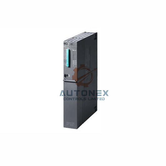
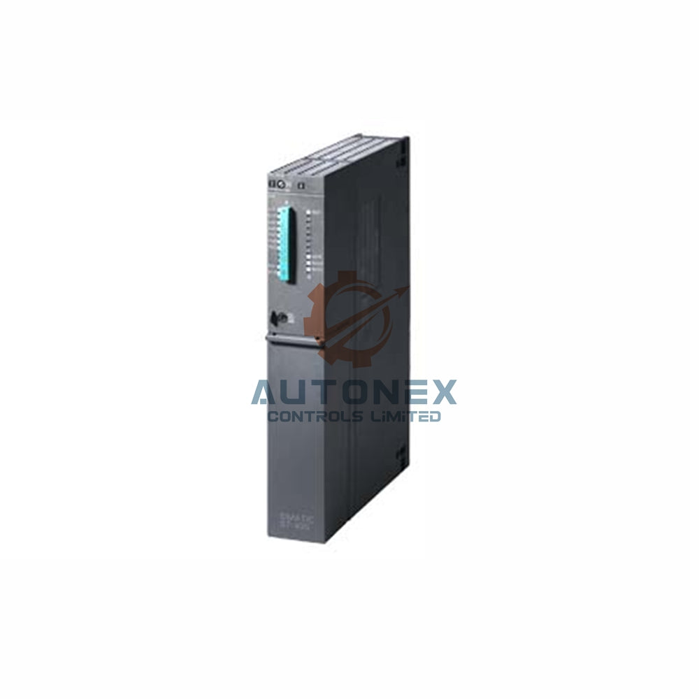
L’adaptateur de communication 1769-SM2 joue le rôle essentiel de traducteur entre les contrôleurs de classe Logix et le réseau Drive Serial Interface (DSI). Cette interface cible spécifiquement la gamme de variateurs PowerFlex 4, qui comprend les modèles courants PowerFlex 40, 4M et 400, et facilite à la fois les messages explicites et l’échange cyclique de données d’E/S. Un avantage notable réside dans son alimentation : le module puise toute l’énergie nécessaire directement sur le bus Compact I/O, ce qui supprime la nécessité d’une alimentation séparée et simplifie ainsi la conception des armoires de commande. Les ingénieurs doivent toutefois garder à l’esprit que le protocole DSI utilise une couche physique RS-485. Dans les configurations Multi-Drive, le débit est plafonné à 19,2 kbit/s. Cette limitation de vitesse entraîne par conséquent des cycles d’interrogation plus longs que ceux des réseaux Ethernet industriels modernes, un facteur qui exige une attention particulière dans les applications soumises à des contraintes temporelles strictes.
Décodage du matériel 1769-SM2 et de l’infrastructure de communication DSI
Le module 1769-SM2 sert essentiellement de passerelle entre le fond de panier du contrôleur Logix et le réseau Drive Serial Interface (DSI). Il est spécialement conçu pour la gamme de variateurs PowerFlex 4, notamment les séries PowerFlex 40, 4M et 400, et prend en charge aussi bien les messages explicites que le transfert de données d’E/S. Ce module est alimenté directement par le bus Compact I/O, ce qui élimine le besoin d’une alimentation externe et simplifie l’agencement de l’armoire. Le protocole DSI fonctionne lui-même sur une couche physique RS-485, avec un débit maximal de 19,2 kbit/s en mode Multi-Drive, une caractéristique essentielle à prendre en compte lors du calcul des temps de mise à jour du réseau dans les applications à haute vitesse. Il faut garder à l’esprit que le DSI en mode Multi-Drive fonctionne à ce débit de 19,2 kbit/s, ce qui entraîne des cycles d’interrogation plus longs que ceux des réseaux Ethernet industriels modernes, un facteur à considérer dans les processus soumis à des contraintes temporelles.
Un seul variateur ou plusieurs : choix architecturaux et évolutivité du système
Une configuration correcte du système commence par le sélecteur physique de mode de fonctionnement (SW2) situé sur le module 1769-SM2. La position « 1X » active le mode Single-Drive, créant une liaison dédiée individuelle où chacun des trois canaux disponibles commande un seul PowerFlex 40. À l’inverse, le basculement du sélecteur sur « 5X » active le mode Multi-Drive, transformant chaque canal en segment RS-485 monté en guirlande, capable de superviser jusqu’à cinq variateurs. Ainsi, un seul module 1769-SM2 peut commander centralement jusqu’à 15 variateurs PowerFlex 40, ce qui réduit considérablement les coûts matériels et l’espace occupé dans l’armoire pour les machines complexes à plusieurs axes. En outre, ce module offre une grande souplesse : chaque canal peut être reconfiguré en maître Modbus RTU via les paramètres 07, 22 et 37, permettant de communiquer avec jusqu’à 31 appareils esclaves, tels que les variateurs PowerFlex de classe 7 à puissance supérieure.

Ajustements essentiels des paramètres pour une commande fluide des variateurs
Pour que le PowerFlex 40 reconnaisse les commandes du 1769-SM2, il faut reprogrammer son jeu de paramètres internes afin de donner la priorité au port de communication. La configuration repose principalement sur la modification du paramètre 36 - [Start Source] et du paramètre 38 - [Speed Reference], en attribuant à chacun la valeur « 5 » afin de sélectionner le port RS485 (DSI). Cette action désactive de fait les bornes de commande locales et place le variateur sous l’autorité du réseau. Parallèlement, dans le module 1769-SM2 lui-même, les paramètres de configuration des E/S (07, 22 et 37) doivent être ajustés pour correspondre au nombre réel de variateurs physiquement raccordés à chaque canal. Par exemple, si trois variateurs sont montés en guirlande sur le canal 1, le paramètre 07 doit être réglé sur « 3 » pour désigner les variateurs 0 à 3. De plus, chaque variateur esclave doit posséder une adresse de nœud unique, attribuée via le paramètre A104 - [Comm Node Addr], afin de garantir des voies de communication sans ambiguïté.
Configuration des actions en mode inactif et de la gestion des défauts pour une exploitation sûre
La définition du comportement du système en cas de défaut ou d’état d’inactivité du contrôleur est un élément essentiel des réseaux industriels, et le 1769-SM2 offre des mécanismes robustes à cet effet. Les paramètres 04, 19 et 34 — intitulés [Idle Action 1, 2, 3] — définissent la réponse de chaque canal lorsque le contrôleur passe en mode Programme ou perd la communication. Par défaut, ces paramètres sont réglés sur « Fault » (valeur 0), ce qui force les variateurs connectés à se mettre en défaut et à s’arrêter en roue libre. Ce réglage par défaut garantit un niveau de sécurité maximal en cas d’événement imprévu. Toutefois, un ingénieur peut choisir de les reconfigurer sur « Stop » (valeur 1), ce qui commande une décélération contrôlée sans générer de défaut. Cette solution est particulièrement avantageuse pour les processus nécessitant un redémarrage rapide, car elle évite de devoir réinitialiser manuellement le défaut.
Garantir l’intégrité du signal : pratiques de câblage et stratégies de mise à la terre
Le câblage physique du réseau DSI entre le 1769-SM2 et les variateurs PowerFlex 40 exige une planification minutieuse afin de préserver l’intégrité du signal sur le bus RS-485. Le module fournit des connecteurs RJ45 pour chaque canal, et Rockwell Automation recommande d’utiliser soit le câble 22-RJ45CBL-C20, soit les borniers AK-U0-RJ45-TB2P pour le câblage fourni par l’utilisateur. Pour garantir une communication fiable, la mise à la terre correcte du blindage du câble réseau est impérative. Elle est généralement réalisée en reliant un fil de drain du bornier du module à une surface conductrice mise à la terre. Il est important de ne raccorder le blindage du câble au châssis qu’en un seul point ; cette pratique évite les boucles de masse, source fréquente de bruit susceptible de corrompre les paquets de données dans les environnements industriels. En outre, le 1769-SM2 intègre une résistance de terminaison, et une résistance supplémentaire doit être installée sur le dernier variateur de la liaison en guirlande afin de prévenir efficacement les réflexions du signal.
Intégration avancée : messagerie explicite et mise en œuvre de la logique à relais
Au-delà du contrôle élémentaire des E/S, le 1769-SM2 prend en charge la messagerie explicite, permettant aux utilisateurs de lire et d’écrire les paramètres des variateurs à des fins de diagnostic et de configuration dynamique. Cette fonctionnalité est accessible via la logique à relais au moyen d’instructions MSG. Toutefois, sa disponibilité dépend de l’automate hôte ; par exemple, elle est prise en charge par les processeurs CompactLogix -L31, -L32E et -L35E, mais pas par les modèles -L20 et -L30. Lors de la programmation, l’ingénieur doit mapper soigneusement les tableaux de données d’entrée et de sortie du 1769-SM2, qui contiennent les mots Commande logique, Référence, État et Retour pour chaque variateur. Dans l’environnement CompactLogix, la référence est transmise sous forme d’un entier de 16 bits représentant la valeur au format xxx.x Hz. Ainsi, une valeur logique de 300 correspond à une consigne de vitesse de 30,0 Hz pour le PowerFlex 40. Ce mappage des données exige une attention rigoureuse aux types de données et aux facteurs d’échelle dans la base de données des tags de l’automate afin de garantir des performances précises du variateur.

Scénario d’application : système de convoyeurs Multi-Drive
Une installation de manutention a mis en œuvre le 1769-SM2 avec des variateurs PowerFlex 40 pour contrôler un système de convoyeurs à 12 zones. En mode Multi-Drive, un seul module gérait 12 variateurs répartis sur trois canaux, chaque canal contrôlant quatre variateurs en configuration en guirlande. L’équipe d’ingénierie a configuré les actions en veille sur « Arrêt » plutôt que sur « Défaut », afin d’éviter les accumulations de matériaux lors des modifications du programme de l’automate. Une messagerie explicite a été mise en œuvre pour les réglages de paramètres à distance, permettant aux opérateurs d’ajuster précisément les profils d’accélération et de décélération sans accéder physiquement aux variateurs. Cette solution a réduit de 40 % l’espace occupé dans l’armoire de commande par rapport à un câblage point à point traditionnel et a simplifié la maintenance grâce à des diagnostics centralisés.
Conclusion
Le module 1769-SM2 offre une solution robuste et économique pour intégrer les variateurs PowerFlex 40 aux systèmes de commande CompactLogix et MicroLogix. Sa flexibilité en modes Single-Drive et Multi-Drive, associée à des réponses aux défauts configurables et à des fonctionnalités de messagerie explicite, le rend adapté à un large éventail d’applications d’automatisation industrielle. Les ingénieurs doivent examiner attentivement les limites de vitesse du réseau lors de la conception d’applications à haute vitesse et privilégier des pratiques de câblage appropriées afin de garantir une communication fiable. À mesure que les réseaux industriels continuent d’évoluer, le protocole DSI demeure une option viable pour les applications où la commande déterministe et la rentabilité sont essentielles.
Foire aux questions
Q1 : Quel est le nombre maximal de variateurs PowerFlex 40 qu’un seul module 1769-SM2 peut commander ?
Un seul module 1769-SM2 peut commander jusqu’à 15 variateurs PowerFlex 40 en mode Multi-Drive, avec cinq variateurs par canal sur trois canaux.
Q2 : Puis-je utiliser un HIM DSI avec les variateurs lorsqu’ils fonctionnent en mode Multi-Drive ?
Non, les périphériques DSI supplémentaires, tels que le HIM PowerFlex 4-Class ou le convertisseur série 22-SCM-232, ne peuvent pas être utilisés lorsque le module fonctionne en mode Multi-Drive, car les ports RS-485 sont utilisés pour le raccordement en guirlande.
Q3 : Comment configurer le PowerFlex 40 pour accepter les commandes du module 1769-SM2 ?
Réglez le paramètre 36 – [Source de démarrage] et le paramètre 38 – [Référence de vitesse] sur « 5 » (port de communication). De plus, chaque variateur nécessite une adresse de nœud unique, définie via le paramètre A104 – [Adresse du nœud de communication].
Q4 : Que se passe-t-il lorsque le contrôleur passe en mode Programme ou perd la communication ?
Par défaut, les variateurs se mettent en défaut et s’arrêtent en roue libre. Toutefois, les paramètres 04, 19 et 34 [Action au repos] peuvent être configurés sur « Stop » (valeur 1), ce qui commande une décélération contrôlée sans générer de défaut.
Q5 : Quels processeurs CompactLogix prennent en charge la messagerie explicite avec le 1769-SM2 ?
La messagerie explicite est prise en charge par les processeurs CompactLogix améliorés, notamment les modèles -L31, -L32E et -L35E. Les processeurs -L20 et -L30 NE prennent PAS en charge la fonctionnalité de messagerie explicite.
Coordonnées
Ventes : sales@nex-auto.com
Téléphone : +86 153 9242 9628
Partenaire
NexAuto Technology Limited : https://www.nex-auto.com/
Consultez ci-dessous les articles populaires pour plus d’informations sur AutoNex Controls

