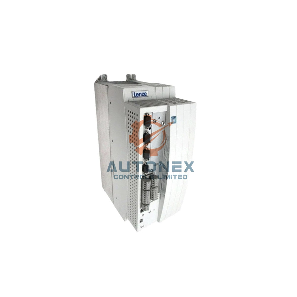
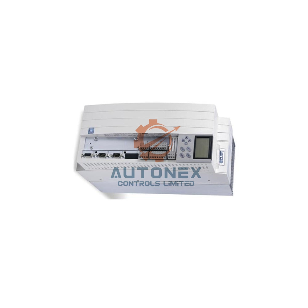
راهنمای شروع سریع Allen-Bradley PowerFlex 525: نصب، سیمکشی و راهاندازی
Allen-Bradley PowerFlex 525 یک نقطه عطف در اتوماسیون صنعتی است که عملکرد قوی را در یک بسته جمع و جور ارائه میدهد. به عنوان یک حرفهای اتوماسیون با بیش از پانزده سال تجربه میدانی، صدها عدد از این درایوها را در کاربردهای مختلف به کار گرفتهام. اتصال EtherNet/IP داخلی و گزینههای پیکربندی انعطافپذیر آنها را برای کنترل ساده موتور و سیستمهای خودکار پیچیده ایدهآل میکند. این راهنمای عملی دانش ضروری نصب را از مستندات رسمی و تجربه کاربردی استخراج کرده است.
ایمنی اول: اقدامات احتیاطی ضروری
تنها تکنسینهای برق مجاز باید نصب و راهاندازی درایو را انجام دهند. همیشه برق را قطع کرده و پنج دقیقه صبر کنید تا خازنها تخلیه شوند قبل از دست زدن به قطعات. اطمینان حاصل کنید که زمینکردن مطابق با استانداردهای NEC و کدهای برق محلی است. من توصیه میکنم از تستر ولتاژ برای تأیید قطع برق استفاده کنید، زیرا این گام ساده از بروز بسیاری از موقعیتهای خطرناک در محیطهای صنعتی جلوگیری میکند.

روشهای بهینه نصب
درایو را به صورت عمودی روی یک سطح صاف نصب کنید تا جریان هوای خنککننده کافی تأمین شود. حداقل 50 میلیمتر فاصله بالاو پایین دستگاه را حفظ کنید. دمای محیط باید بین -20 درجه سانتیگراد تا +50 درجه سانتیگراد برای عملکرد مطلوب باقی بماند. بر اساس تجربه من، بسیاری از مشکلات حرارتی ناشی از تهویه ناکافی است نه خرابی درایو. برای محیطهای سخت که شامل رطوبت، گرد و غبار یا عناصر خورنده هستند، استفاده از محفظههای دارای استاندارد NEMA را در نظر بگیرید.
تکنیکهای صحیح زمینکردن
ترمینال زمین حفاظتی را مستقیماً به سیستم زمین تأسیسات خود با استفاده از سیم مسی با اندازه مطابق با الزامات NEC متصل کنید. برای درایوهای تا 10 اسب بخار، معمولاً از هادیهای 14-12 AWG استفاده کنید. نکته مهم این است که برای سیستمهای زمیندار با امپدانس، باید جامپر MOV را برای جلوگیری از آسیب بردارید. من مشکلات زیادی در زمینه EMI را صرفاً با تأیید صحت اتصال زمین و رسانایی آن حل کردهام.
مشخصات سیمکشی قدرت
برای کاربردهای سهفاز، سیمهای قدرت را به ترمینالهای R/L1، S/L2 و T/L3 متصل کنید. مدلهای انتخابی از عملکرد تکفاز با استفاده از R/L1 و S/L2 پشتیبانی میکنند. همیشه از سیم مسی با درجه حرارت 75 درجه سانتیگراد و اندازه مناسب استفاده کنید: 14-10 AWG برای سیستمهای 200-240 ولت، 14-8 AWG برای کاربردهای 480 ولت. فیوزها یا مدارشکنهای مناسب برای حفاظت مدار شاخهای نصب کنید. از تجربه من، ترمینالهای بیش از حد سفت شده به اندازه اتصالات شل مشکل ایجاد میکنند - در صورت امکان از ابزارهای گشتاور کالیبره شده استفاده کنید.
بهترین روشهای سیمکشی کنترل
ورودیهای آنالوگ سیگنالهای 0-10 ولت یا 4-20 میلیآمپر را از طریق تنظیم جامپر انتخاب میکنند. ورودیهای دیجیتال هر دو حالت sinking و sourcing را پشتیبانی میکنند که توسط جامپر A051 تعیین میشود. از کابلهای پیچخورده شیلددار مانند Belden 8760 برای حفظ یکپارچگی سیگنال استفاده کنید. نکته مهم: سیمکشی کنترل را جدا از هادیهای قدرت انجام دهید، زیرا جداسازی نادرست باعث 80٪ مشکلات نویز در میدانی است که من تجربه کردهام.
چکلیست تأیید پیش از راهاندازی
اطمینان حاصل کنید که تمام اتصالات الکتریکی مطابق مشخصات گشتاور هستند. دادههای نامی موتور شامل ولتاژ، جریان و فرکانس پایه را مستند کنید. شرایط محیطی را در محدوده عملیاتی حفظ کنید. تنظیمات جامپر را مطابق طرح کنترل خود تنظیم کنید. توصیه میکنم یک چکلیست استاندارد برای تأسیسات خود ایجاد کنید تا در نصبهای متعدد ثبات حفظ شود.
پیکربندی پارامترهای ضروری
در حالی که PowerFlex 525 با تنظیمات پیشفرض کارخانه عرضه میشود، پارامتردهی صحیح عملکرد بهینه را تضمین میکند. پارامترهای کلیدی شامل A101/A102 برای زمانبندی شتاب/کاهش سرعت، P031-P034 برای تطبیق دادههای نامی موتور و P037 برای تنظیم خودکار موتور هستند. همیشه P033 را روی جریان نامی موتور برای حفاظت مناسب در برابر اضافهبار تنظیم کنید. در تجربه من، ورود نادرست دادههای موتور باعث بیشتر مشکلات عملکردی در راهاندازی میشود.

مبانی عملکرد صفحهکلید
صفحهکلید یکپارچه کنترل شروع/توقف و تنظیم سرعت را از طریق پتانسیومتر داخلی فراهم میکند. فرمانهای جلو/عقب به راحتی در دسترس هستند اما میتوانند از طریق پارامتر A544 غیرفعال شوند. اختیار کنترل میتواند به ترمینالها یا ارتباطات شبکه منتقل شود. برای آموزش، من همیشه ابتدا با کنترل صفحهکلید شروع میکنم و سپس به عملیات خودکار منتقل میشوم.
مشکلات رایج راهاندازی و راهحلها
اگر موتور روشن نشد، مطمئن شوید A051 با انتخاب روش کنترل شما مطابقت دارد. در هنگام اعمال برق، خطاهای undervoltage یا overvoltage را بررسی کنید. تأیید کنید P033 با جریان نامی موتور مطابقت دارد. بسیاری از خرابیهای ظاهری در درایوها در واقع ناشی از تنظیمات نادرست پارامترها هستند نه نقص سختافزاری. مستندسازی فایلهای پارامتر قبل از تغییرات، عیبیابی را به طور قابل توجهی ساده میکند.
سناریوی کاربردی دنیای واقعی
یک تصفیهخانه فاضلاب با قطعهای مکرر و مزاحم در دمندههای هوادهی مواجه شد. بررسیها نشان داد زمانبندی شتابدهی نادرست و پارامترهای داده موتور ناقص بودند. پس از انجام تنظیم خودکار و وارد کردن مشخصات صحیح موتور، عملکرد درایو بلافاصله تثبیت شد. این مورد نشان میدهد که راهاندازی صحیح چگونه از اختلالات عملیاتی جلوگیری میکند.
دیدگاه و روندهای صنعت
ادغام EtherNet/IP به طور مستقیم در معماری درایو نمایانگر حرکت صنعت به سمت سیستمهای متصل است. نصبهای مدرن به طور فزایندهای به کنترل و نظارت مبتنی بر شبکه متکی هستند. با این حال، اصول پایه الکتریکی تغییر نکردهاند - سیمکشی صحیح، زمینکردن و پارامتردهی همچنان موفقیت نصب را بدون توجه به پروتکل ارتباطی تعیین میکنند.
سؤالات متداول
آیا درایوهای PowerFlex 525 میتوانند با برق تکفاز کار کنند؟
مدلهای انتخابشده از ورودی تکفاز پشتیبانی میکنند، اما باید شمارههای کاتالوگ و جداول رتبهبندی خاص را بررسی کنید. ممکن است برای برخی کاربردها کاهش ظرفیت اعمال شود.
چه زمانی باید مقاومت ترمزی نصب کنم؟
برای بارهای با اینرسی بالا یا کاربردهایی که نیاز به کاهش سرعت سریع دارند، از مقاومتهای ترمزی استفاده کنید. سیکلهای کاری استاندارد معمولاً به قطعات ترمز اضافی نیاز ندارند.
چگونه پارامترهای پیشفرض کارخانه را بازیابی کنم؟
پارامتر P053 را روی مقدار 2 تنظیم کنید و برق را قطع و وصل کنید. همیشه قبل از بازنشانی، از پارامترهای سفارشی نسخه پشتیبان تهیه کنید، زیرا این فرآیند تمام دادههای پیکربندی را پاک میکند.
آیا کنترل اترنت بلافاصله در دسترس است؟
بله، عملکرد EtherNet/IP به صورت تعبیهشده وجود دارد. پارامترها را در گروه ارتباطات پیکربندی کنید و A541 را به طور مناسب برای عملکرد شبکه تنظیم کنید.
چه نگهداریای اطمینان از قابلیت اطمینان بلندمدت را فراهم میکند؟
اتصالات ترمینال را به طور منظم بررسی کنید، پرههای خنککننده را تمیز کنید، عملکرد فن را تأیید کنید و یکپارچگی پارامترها را بررسی کنید. پارامترهای عملیاتی را مستند کنید تا در صورت نیاز به سرعت بازیابی شوند.
برای اطلاعات بیشتر، موارد محبوب زیر را در Autonexcontrol بررسی کنید


