

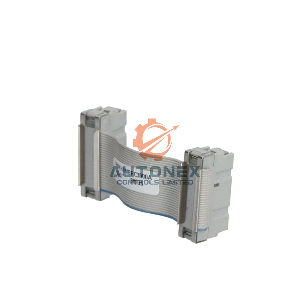
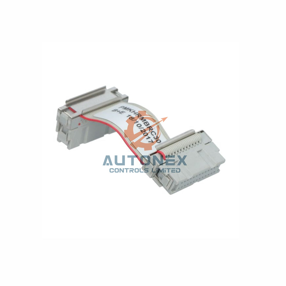


تسلط بر سیمکشی I/O تعبیهشده 1769-L16ER برای کنترلرهای CompactLogix
راهنمایی در منابع مستندات رسمی راکول اتوماسیون
راکول اتوماسیون تمام انتشارات فنی را از طریق مرکز سازگاری محصول و دانلود (PCDC) متمرکز میکند. وبسایت رسمی به عنوان مخزن اصلی نمودارهای سیمکشی و مراجع نصب عمل میکند. کتابخانه ادبیات شامل انتشار 1769-UM011 است که جزئیات کامل نصب این مدل کنترلر را ارائه میدهد.
کاربران باید مستقیماً به بخش دفترچهها رفته و اسناد را با فیلتر «دستورالعملهای نصب» جستجو کنند تا مرجع سیمکشی صحیح را بیابند. طرح بلوک ترمینال I/O تعبیهشده به وضوح در صفحه دوازدهم نشان داده شده است. بررسی وضعیت بازبینی قبل از دانلود هر فایل از بروز مشکلات سازگاری جلوگیری میکند. آخرین بازبینی شامل بهروزرسانیهای ضروری برای پارامترهای مقیاسبندی ورودی آنالوگ است. بازبینی 3.2 خطاهای مهم مشخصات ولتاژ حالت مشترک را اصلاح کرد.
درک پینآوت و پیکربندی بلوک ترمینال
1769-L16ER شامل یک بلوک ترمینال بیست پینی قابل جدا شدن است که از عملکردهای I/O تعبیهشده پشتیبانی میکند. ترمینالهای صفر تا هفت به کانالهای ورودی دیجیتال متصل میشوند. ترمینالهای هشت تا یازده از عملیات شمارنده با سرعت بالا پشتیبانی میکنند. ترمینالهای دوازده تا پانزده به عنوان نقاط خروجی دیجیتال سینک عمل میکنند. هر خروجی تا 2.0 آمپر به طور مداوم در 24 ولت DC ارائه میدهد.
ورودیهای آنالوگ تعبیهشده در ترمینالهای شانزدهم و هفدهم قرار دارند. این کانالهای آنالوگ از طریق پیکربندی نرمافزاری سیگنالهای 0-10 ولت یا 4-20 میلیآمپر را میپذیرند. ترمینال هجدهم ولتاژ مرجع +5 ولت برای تحریک سنسور فراهم میکند. ترمینالهای نوزدهم و بیستم به عنوان مسیرهای بازگشت مشترک عمل میکنند. رعایت دقیق سیمکشی، اطمینان از صحت سیگنال در محیطهای صنعتی را تضمین میکند.

مراحل ساده برای دانلود نمودارهای سیمکشی
ابتدا با مرورگر مورد علاقه خود به وبسایت ادبیات راکول اتوماسیون دسترسی پیدا کنید. عبارت "1769-L16ER" را در کادر جستجو وارد کرده و کلید اینتر را فشار دهید. از نتایج موجود، برگه «دستورالعملهای نصب» را انتخاب کنید. سند شماره 1769-IN001B-EN-P را از فهرست پیدا کنید.
برای ذخیره فایل PDF مستقیماً روی دستگاه خود، روی آیکون دانلود کلیک کنید. همچنین میتوانید از ویژگی «مشاهده آنلاین» برای دسترسی فوری به مرجع استفاده کنید. مقدار چکسام را برای تأیید صحت فایل بررسی کنید. چکسام نسخه فعلی برابر با 0x7F3A است. نمودار سیمکشی در صفحه هجدهم دفترچه راهنما قرار دارد. برای تأیید سازگاری سختافزار، آن را با برچسب محصول مقایسه کنید. یک نسخه محلی برای دسترسی آفلاین به نگهداری ذخیره کنید.
مشخصات الکتریکی و راهنمای محاسبه بار
ورودیهای دیجیتال تعبیهشده در ولتاژ نامی ۲۴ ولت DC با محدوده قابل قبول ۱۰-۳۰ ولت کار میکنند. امپدانس ورودی تقریباً ۴.۷ کیلو اهم است تا جریان کشش را بهطور مؤثر محدود کند. هر ورودی در شرایط ولتاژ نامی حدود ۵.۱ میلیآمپر مصرف میکند. خروجیها تا ۲.۰ آمپر به ازای هر نقطه با محدودیت جریان کل ۸ آمپر تأمین میکنند.
رلههای خارجی به دیودهای فلیبک برای حفاظت ترانزیستور خروجی نیاز دارند. ورودیهای آنالوگ دقت ۱۴ بیت با دقت ±۰.۵٪ ارائه میدهند. زمان اسکن ورودی/خروجی تعبیهشده به ۲ میلیثانیه در هر اسلات میرسد. این پاسخ سریع بهطور مؤثر از برنامههای حرکت با سرعت بالا پشتیبانی میکند. کل توان تلفشده در شرایط بار حداکثر به ۳.۲ وات میرسد. مدیریت حرارتی مناسب برای طراحی کابینت کنترل ضروری است.
خطاهای رایج سیمکشی و تکنیکهای عیبیابی
بسیاری از مهندسان بهطور ناخواسته سیمهای مشترک و سیگنال را برای ورودیهای آنالوگ جابجا میکنند. در نتیجه، ماژولها خوانشهای ناپایدار گزارش میدهند یا شرایط خطای بیشمحدوده را فعال میکنند. برای انتقال سیگنال آنالوگ از کابلهای جفتپیچشده شیلددار استفاده کنید تا از این مشکل جلوگیری شود. اتصال شیلد به زمین در یک نقطه، تداخل حلقه زمین را بهطور قابل توجهی کاهش میدهد.
اشتباه رایج دیگر، تجاوز از جریان خروجی مجاز هر کانال است. در نتیجه، ماژول خاموشی حرارتی را فعال کرده و کد خطای ۲۱ را ثبت میکند. استفاده از رلههای واسطه عمر خروجی را بهطور قابل توجهی افزایش میدهد. پیچهای ترمینال شل مشکلات اتصال متناوب ایجاد میکنند. هر پیچ را طبق مستندات با گشتاور ۰.۵۶ نیوتنمتر سفت کنید. بازرسیهای دورهای تصویربرداری حرارتی میتوانند اتصالات شل را قبل از وقوع خرابی شناسایی کنند.
ادغام معماری استراتژیک سیستم
این کنترلر بهطور یکپارچه با شبکههای Ethernet/IP که پیکربندیهای ورودی/خروجی توزیعشده را پشتیبانی میکنند، ادغام میشود. ورودی/خروجی تعبیهشده نقاط کنترل محلی برای اتصالات حسگرهای حیاتی فراهم میکند. حسگرهای مجاورت را به ورودیهای دیجیتال برای نظارت بر موقعیت نقاله متصل کنید. از خروجیهای آنالوگ برای راهاندازی مستقیم درایوهای فرکانس متغیر استفاده کنید.
سیستم تا سی ماژول ورودی/خروجی فشرده 1769 اضافی را پشتیبانی میکند. ورودی/خروجی تعبیهشده به تخصیص اسلات شاسی محلی ثابت باقی میماند. نقاط تعبیهشده را برای مدارهای توقف اضطراری یا عملکردهای قفل ایمنی اختصاص دهید. این استراتژی زمان پاسخ قطعی زیر ۵۰ میلیثانیه را تضمین میکند. پورتهای دوگانه اترنت کنترلر امکان توپولوژیهای حلقهای در سطح دستگاه را فراهم میکنند. افزونگی شبکه بدون هزینه سختافزاری اضافی حاصل میشود.

ویژگیهای عملکردی و محدودههای عملیاتی محیطی
1769-L16ER در دماهای محیطی از -20 درجه سانتیگراد تا 65 درجه سانتیگراد به طور قابل اطمینان کار میکند. تحمل رطوبت نسبی از 5٪ تا 95٪ بدون تراکم است. مقاومت در برابر شوک با رتبه 30G برای آزمایشهای 11 میلیثانیه مطابقت دارد. تحمل لرزش مطابق با IEC 60068-2-6 در سطوح اوج 5G است.
مدارهای ورودی/خروجی تعبیهشده دارای ایزولاسیون نوری با رتبه 2500 ولت RMS هستند. این ایزولاسیون از بَکپلین در برابر رویدادهای گذرای ولتاژ بالا محافظت میکند. میانگین زمان بین خرابیها (MTBF) برابر با 1.2 میلیون ساعت است. این سیستم برای محیطهای تولید مداوم به طور مؤثر مناسب است. ریپل منبع تغذیه باید زیر 5٪ برای رفتار عملیاتی پایدار باقی بماند. جریان راهاندازی محدود به 10 آمپر برای 1 میلیثانیه در توالیهای راهاندازی است.
نیازمندیها و سازگاری نسخه فرمویر
نسخه فرمویر 31.011 یا بالاتر تمام ویژگیهای ورودی/خروجی تعبیهشده را به طور کامل پشتیبانی میکند. ضرایب مقیاسبندی آنالوگ در نسخه 32.021 بهبود یافتهاند. پروژههای Studio 5000 را دقیقاً با نسخه فرمویر کنترلر بهروزرسانی کنید. در غیر این صورت، ممکن است خطاهای پیکربندی ورودی/خروجی هنگام عملیات دانلود ظاهر شود.
نمودار سیمکشی در تمام نسخههای فرمویر ثابت باقی مانده است. یادداشتهای انتشار را برای هرگونه تغییر عملکرد ترمینال بررسی کنید. ترمینال هجده در نسخه v33 برای مرجع قابل کالیبراسیون بازتعریف شد. برای انجام ایمن بهروزرسانی فرمویر از ControlFLASH استفاده کنید. قبل از شروع هر فرآیند بهروزرسانی، پروژههای موجود را پشتیبانگیری کنید. پس از ارتقا، عملکرد هر کانال ورودی/خروجی را از طریق روالهای تست تأیید کنید.
مطالعه موردی کاربرد خط بستهبندی
یک کارخانه بستهبندی مواد غذایی از ورودی/خروجی تعبیهشده 1769-L16ER برای کنترل سیستم نقاله استفاده کرد. ورودیهای دیجیتال حضور محصول را از طریق آرایههای حسگر فوتوالکتریک نظارت کردند. ورودیهای آنالوگ سطح پر شدن را با استفاده از فناوری مبدل اولتراسونیک اندازهگیری کردند. خروجیها شیرهای سلونوئیدی را برای عملیات انحراف بسته فعال کردند.
سیستم بدون کاهش عملکرد، 120 محصول در دقیقه پردازش کرد. پس از شش ماه، عملکرد ورودی/خروجی در محدوده مشخصات کارخانه باقی ماند. گزارشهای نگهداری هیچ خرابی ناشی از مشکلات سیمکشی ثبت نکردند. کارخانه این پلتفرم را برای خطوط تولید آینده استاندارد کرد. در هر دوره نگهداری پیشگیرانه، نمودار سیمکشی مرجع قرار گرفت. این روش زمان عیبیابی را چهل درصد کاهش داد.
لوازم جانبی ضروری و توصیههای مدیریت کابل
برای نیازهای ترمینیشن سریع از کابلهای پیشبرش 1492-ACABLE-020 استفاده کنید. برای کاربردهای اتصال میدانی از سیم رشتهای 16 AWG بهره ببرید. استفاده از ترمینالهای فِرول به منظور بهبود اطمینان گیره پیچ به شدت توصیه میشود. طول کابل برای سیگنالهای آنالوگ نباید از 100 متر تجاوز کند. سیگنالهای دیجیتال میتوانند تا 300 متر با اجرای مناسب شیلدینگ گسترش یابند.
سرکوبگرهای ولتاژ گذرا را روی مدارهای خروجی بار القایی نصب کنید. کیت 1769-ECR یک درپوش انتهایی برای موقعیتهای ترمینال استفادهنشده فراهم میکند. از بستهای زیپی برای مرتبکردن دستههای سیم استفاده کنید. هر سیم را با مارکرهای حرارتی برچسبگذاری کنید تا شناسایی آسان شود. پیروی از این روشها پایداری و قابلیت اطمینان بلندمدت سیستم را تضمین میکند.
انطباق مقررات و گواهیهای ایمنی
1769-L16ER دارای گواهیهای UL، CE و ATEX برای عملکرد در مکانهای خطرناک است. نمودار سیمکشی مطابق با الزامات برق کلاس ۲ NEC است. زمین کردن باید با استانداردهای IEC 61131-2 برای نصبهای کنترل صنعتی مطابقت داشته باشد. ورودی/خروجی تعبیهشده برای درجه آلودگی محیطی ۲ واجد شرایط است.
موانع ایزولاسیون مطابق با معیارهای عایق تقویتشده طبق مشخصات EN 61010-1 هستند. کابلهای ولتاژ بالا را جدا از مسیرهای سیمکشی ورودی/خروجی عبور دهید. حداقل ۱۰ میلیمتر فاصله بین هادیهای برق و سیگنال حفظ کنید. از هستههای فریت روی کابلهای برق برای کاهش مؤثر تداخل الکترومغناطیسی استفاده کنید. تست دورهای عایقکاری سالانه توصیه میشود. این پروفایل انطباق، نصب ماشینآلات جهانی را بدون تغییر پشتیبانی میکند.
پشتیبانی فنی و منابع جامعه
پایگاه دانش راکول بیش از ۵۰۰ مقاله درباره موضوعات سیمکشی کنترلر 1769 دارد. خط پشتیبانی TechConnect بهصورت ۲۴/۷ برای مسائل حیاتی در دسترس است. انجمنهای کاربران نکات عملی سیمکشی و نمونه کدها را بهطور مکرر به اشتراک میگذارند. پروژه نمونه "Wiring_Check" هر اتصال را بهطور خودکار اعتبارسنجی میکند. این پروژه را از کتابخانه نمونه کد دانلود کنید.
جامعه انجمن شامل ۲۳۰۰ عضو فعال است که بهطور منظم درباره موضوعات ورودی/خروجی بحث میکنند. بسیاری از اعضا تجربه موفق دانلود نمودار سیمکشی را گزارش کردهاند. مشاوره همتا بهطور مؤثر منابع مستندات رسمی را تکمیل میکند. برای دریافت اطلاعیههای بهروزرسانی، در خبرنامه ماهانه مشترک شوید. در وبینارها برای آموزشهای عملی سیمکشی شرکت کنید.
خلاصه اجرای بهترین روشها
دسترسی به نمودار سیمکشی ورودی/خروجی تعبیهشده 1769-L16ER از طریق پورتالهای رسمی ساده باقی میماند. از آخرین نسخه برای تأیید دقیق تخصیص پینها استفاده کنید. پایاندهی صحیح و محاسبات بار از بروز مشکلات رایج در میدان جلوگیری میکند. عوامل محیطی و درجهبندی ایزولاسیون مستقیماً بر طول عمر سیستم تأثیر میگذارند.
ورودی/خروجی تعبیهشده را بهطور استراتژیک در طراحی معماری سیستم خود ادغام کنید. از دانش جامعه و پشتیبانی راکول برای سناریوهای پیچیده بهره ببرید. بازبینی دورهای روشهای سیمکشی، اثربخشی کلی تجهیزات را افزایش میدهد. این رویکرد حداکثر زمان کارکرد و حداقل وقوع خرابیهای ناگهانی را تضمین میکند. اجرای این دستورالعملها عملکرد اتوماسیون پایدار و قوی را تضمین میکند.
راهحل کاربردی: یکپارچهسازی کنترل نقاله
یک سیستم حمل مواد نیاز به کنترل دقیق نقاله با نظارت ایمنی داشت. 1769-L16ER I/O تعبیهشده برای اتصال سنسورهای محلی فراهم کرد. ورودیهای دیجیتال شرایط اضافه بار موتور و وضعیت توقف اضطراری را نظارت کردند. ورودیهای آنالوگ سرعت نقاله را از طریق سیگنالهای بازخورد انکودر پیگیری کردند. خروجیها کنتاکتورهای موتور و نشانگرهای هشدار را کنترل کردند.
سیستم در طول دوازده ماه به 99.9٪ زمان کارکرد دست یافت. این پیکربندی توانایی کنترلر را برای عملیات حیاتی نشان داد. I/O تعبیهشده نیاز به بلوک ترمینال خارجی را حذف کرد و فضای پنل را 25٪ کاهش داد.
سؤالات متداول درباره سیمکشی 1769-L16ER
1. نقشه سیمکشی رسمی 1769-L16ER را کجا میتوانم پیدا کنم؟
نقشه سیمکشی رسمی از طریق مرکز سازگاری و دانلود محصولات Rockwell Automation در دسترس است. به کتابخانه ادبیات مراجعه کنید، "1769-L16ER" را جستجو کنید و با فیلتر "دستورالعملهای نصب" سند 1769-IN001B-EN-P را پیدا کنید.
2. حداکثر جریان مجاز برای خروجیهای دیجیتال چقدر است؟
هر کانال خروجی دیجیتال تا 2.0 آمپر به طور مداوم در 24 ولت DC را پشتیبانی میکند. جریان کل تجمعی در تمام نقاط خروجی نباید از 8 آمپر تجاوز کند تا از شرایط خاموشی حرارتی جلوگیری شود.
3. آیا میتوانم انواع سیگنال ورودی آنالوگ را در یک ماژول ترکیب کنم؟
بله، ورودیهای آنالوگ هر دو سیگنال 0-10 ولت و 4-20 میلیآمپر را قبول میکنند. باید هر کانال را به صورت جداگانه از طریق نرمافزار تنظیم کنید تا با نوع سنسور متصل شده مطابقت داشته باشد.
4. چه عواملی باعث خطاهای ارتباطی متناوب I/O میشوند؟
اتصالات شل ترمینالها اغلب باعث مشکلات متناوب میشوند. اطمینان حاصل کنید که همه ترمینالهای پیچ به گشتاور 0.56 نیوتنمتر محکم شدهاند. همچنین اتصال زمین و پایان شیلد را بررسی کنید.
5. فریمور چگونه بر عملکرد I/O تعبیهشده تأثیر میگذارد؟
نسخههای فریمور کنترل ضرایب مقیاسبندی آنالوگ و تخصیص عملکرد ترمینالها را مدیریت میکنند. همیشه فریمور پروژه Studio 5000 را با فریمور کنترلر مطابقت دهید. یادداشتهای انتشار را برای تغییرات خاص ترمینالها در نسخههای مختلف بررسی کنید.
اطلاعات تماس
برای استعلام در مورد راهحلهای اتوماسیون صنعتی، لطفاً با تیم فروش فنی ما از طریق sales@nex-auto.com تماس بگیرید یا از طریق واتساپ به شماره +86 153 9242 9628 دسترسی پیدا کنید.
شریک: NexAuto Technology Limited
https://www.nex-auto.com/
برای اطلاعات بیشتر در مورد اقلام محبوب زیر به AutoNex Controls مراجعه کنید

