


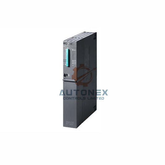
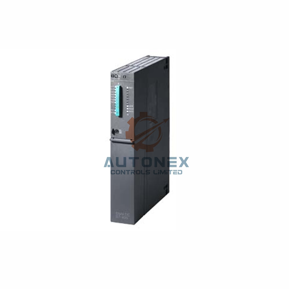


IC693PWR332 Undervoltage Protection: Surge Absorber Guide for High-Power Inductive Load Switching
Industrial automation systems often face hidden electrical threats. The GE Fanuc Series 90-30 platform is widely used in factory automation and control systems. However, the IC693PWR332 power supply can trip during inductive load disconnection. This article explains the root cause and provides practical surge suppression solutions.
Why the IC693PWR332 Trips During Inductive Load Switching
The IC693PWR332 delivers a nominal 12 VDC output. Its input range spans 9.6 to 15 VDC. The ride-through time is at least 10 milliseconds. When a high-power inductive load disconnects, the collapsing magnetic field creates a reverse voltage spike. This transient can pull the supply below the undervoltage threshold. Consequently, the module enters a protective shutdown. The 5 VDC logic output is especially vulnerable to these disturbances.
Calculating Inductive Kickback Energy
The stored energy in an inductive load follows E = ½ × L × I². A typical 24 VDC solenoid with 2.4 H inductance and 0.5 A current stores about 0.3 joules. However, industrial contactors and motor starters often have much higher inductance. A 10 H coil carrying 2 A stores 20 joules. This energy must be dissipated or redirected when the circuit opens. Otherwise, the voltage spike can reach several kilovolts.
Varistor Selection and Installation for Surge Protection
Metal oxide varistors offer a cost-effective clamping solution. Start with the maximum steady-state DC voltage. Choose a varistor voltage rating 10 to 15% above the operating voltage. For a 24 VDC circuit, a 31 VDC maximum continuous rating works well. The clamping voltage at peak current must stay below the IC693PWR332 protective threshold. Also, the varistor must handle the calculated energy per switching event. GE recommends the V39ZA1 model for 28 VDC applications with peak currents under 1 A.

RC Network Design for Contact Protection
RC snubber networks damp high-frequency oscillation. The capacitor absorbs inductive energy while the resistor limits discharge current. For contact protection, use capacitor values from 0.22 to 0.47 µF. Series resistance typically ranges from 10 to 400 Ω. A practical starting point uses 0.5 to 1 µF per ampere of load current. The resistor should initially equal the load DC resistance. However, RC networks across contacts can cause excessive leakage current when open. This approach also delays relay release times significantly.
Hybrid Suppression for Optimal Performance
Combining a small RC network with a varistor provides superior protection. The RC network suppresses initial low-voltage arcing. The varistor then clamps later voltage peaks. This hybrid approach often proves more cost-effective than a single large capacitor. For a 28 VDC application, a 0.068 µF capacitor paired with a V39ZA1 varistor eliminated arcing completely. The capacitor voltage rating should reach 200 to 300 V for AC circuits. Always verify that the suppression device is placed as close as possible to the inductive load.
Installation Best Practices and Verification
Locate the surge absorber directly across the inductive load terminals. This placement minimizes the loop area carrying transient currents. Keep lead lengths under 30 cm to reduce parasitic inductance. After installation, verify performance with an oscilloscope. Measure the peak voltage across the power supply input during load disconnection. The spike should remain below 15 VDC to prevent undervoltage trips. Furthermore, confirm that the ride-through time remains sufficient for the application. Regular inspection of the suppression device is recommended for aging systems.
Field Data and Performance Validation
Field reports indicate that unmitigated inductive switching can generate transients exceeding 300 V. With proper varistor installation, clamping voltages typically remain below 70 V at 1 A. A 0.22 µF/100 Ω RC network suppressed arcing completely in one documented case. Reducing the capacitor to 0.047 µF allowed arcing to initiate at 70 V. These quantified results demonstrate the critical relationship between component sizing and suppression effectiveness. Therefore, engineers must calculate energy requirements precisely for each specific inductive load.
Author Insights and Industry Commentary
From my experience in industrial automation and control systems, undervoltage trips on PLC power supplies are often misdiagnosed as module failures. In reality, the root cause frequently lies in inductive load switching. Engineers should treat surge suppression as a design requirement, not an afterthought. Moreover, the growing use of variable frequency drives and high-power contactors in factory automation makes this issue more common. I recommend a hybrid approach for critical DCS and PLC applications. It balances cost, reliability, and long-term equipment lifespan.
Application Case and Solution Scenario
Consider a factory automation line with multiple 24 VDC solenoids and motor starters. The IC693PWR332 power supply tripped randomly during operation. After installing a V39ZA1 varistor across each inductive load, the trips stopped completely. The clamping voltage stayed below 70 V. In addition, a small RC network further reduced contact arcing. This solution extended relay life and improved overall system reliability. For similar applications, always measure the actual transient with an oscilloscope before selecting components.

Frequently Asked Questions (FAQ)
Q1: What causes the IC693PWR332 to trip during inductive load switching?
A1: The collapsing magnetic field of an inductive load generates a reverse voltage spike. This transient can pull the supply below the undervoltage threshold and trigger a protective shutdown.
Q2: How do I choose the right varistor for my PLC power supply?
A2: Select a varistor voltage rating 10 to 15% above the operating voltage. Ensure the clamping voltage stays below the power supply threshold. Also, verify the varistor can handle the calculated energy per switching event.
Q3: Can an RC network alone protect against inductive kickback?
A3: An RC network can suppress arcing, but it may cause leakage current and delay relay release. For optimal performance, combine a small RC network with a varistor in a hybrid configuration.
Q4: Where should I install the surge absorber?
A4: Install the surge absorber directly across the inductive load terminals. Keep lead lengths under 30 cm to minimize parasitic inductance and maximize effectiveness.
Q5: How do I verify that the suppression solution is working?
A5: Use an oscilloscope to measure the peak voltage across the power supply input during load disconnection. The spike should remain below 15 VDC to prevent undervoltage trips.
Contact Information
For inquiries, please contact us at sales@nex-auto.com or +86 153 9242 9628.
Partner NexAuto Technology Limited: https://www.nex-auto.com/
Check below popular items for more information in AutoNex Controls
