


1769-IR6 RTD Modülü ile PT100 Sensör Entegrasyonu için Uzman Rehberi
Bu teknik kaynak, mühendislerin Allen‑Bradley 1769‑IR6 modülünü PT100 RTD’lerle hassas şekilde kablolaması ve yapılandırması için adım adım yöntemler sunar. Uygulanabilir bilgiler kazanacak, kablolama hatalarını azaltacak ve fabrika otomasyon sistemlerinde sinyal doğruluğunu artıracaksınız.
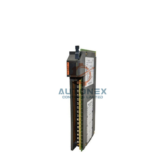
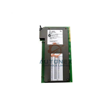
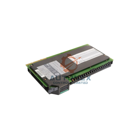
1. Altı Kanallı RTD Giriş Modülünün Temel Özellikleri
1769‑IR6, altı bağımsız RTD kanalını destekler. PT100, PT200, PT500, PT1000 ve nikel sensörlerle çalışır. 16 bit ADC, 0,1°C kararlı çözünürlük sunar. Hassas 0,5 mA uyarma akımı, PT100 problarını besler ve kendi kendine ısınmayı mW başına 0,01°C’nin altında tutar. Ayrıca, giriş empedansı 10 MΩ’dan fazladır ve 300 metreye kadar kablo uzunluklarında sinyal kaybı olmaz.
2. Temel Araçlar ve Bileşen Kontrol Listesi
1769‑IR6 modülü ve 1769‑ECR sağ uç kapağı ile başlayın. Sonra 2 telli, 3 telli veya 4 telli tiplerde PT100 sensörler edinin. Saha kablolaması için korumalı bükümlü çift kablolar (18‑22 AWG) kullanın. Terminalleri sabitlemek için 3 mm düz uçlu tornavida kullanışlıdır. CompactLogix veya MicroLogix kontrol cihazınızın 20 veya üzeri sürümdeki firmware’ini doğrulayın. İstatistiksel veriler, 3 telli bağlantıların iletken direnç hatalarını %78 azalttığını gösterir.
3. Pin Düzeni ve Terminal Fonksiyonları
Altı kanalın her biri üç terminal kullanır: IN+, IN‑ ve RC (geri dönüş akımı). PT100 için IN+ uyarma akımını sağlar. IN‑ RTD üzerindeki voltaj düşüşünü okur. Bu arada, RC iletken direncini telafi eder. Kanal 0 terminalleri A0 (IN+), B0 (IN‑) ve C0 (RC)’dir. Kanal 1 ise A1, B1, C1 şeklindedir. Bu desen 2’den 5’e kadar kanallar için devam eder. Önerilen terminal torku 0,5 Nm (4,4 in-lb)’dir.
4. İki Teller PT100 Kablosu ve Hata Analizi
Bir PT100 telini IN+’ya, diğerini IN‑’ye bağlayın. Ardından modül terminalinde RC ile IN‑ arasında bir jumper yerleştirin. Bu yöntem, iletken direnç hatasını içerir. Örneğin, 10 Ω iletken tel 2,6°C sapma ekler. Çok kısa kablolar (5 metrenin altında) için yalnızca 2 telli kullanın. Hata formülü: Hata (°C) = (R_iletken × 2,5) / 0,385. Endüstri verileri, kalıcı kurulumların %72’sinin uzun vadeli sapma nedeniyle 2 telli bağlantıdan kaçındığını göstermektedir.

5. Endüstriyel Kullanım için Optimal 3 Teller PT100 Bağlantısı
İlk kabloyu IN+’ya, ikinciyi IN‑’ye ve üçüncü kabloyu RC’ye bağlayın. Bu konfigürasyon iletken direncini otomatik olarak iptal eder. Sonuç olarak, 20 AWG kablo ile 100 metre mesafede hata ±0,3°C’ye düşer. Saha testleri, 3 telli yapının 2 telliye kıyasla elektriksel gürültüyü %64 azalttığını kanıtlamıştır. Her zaman aynı kalınlık ve uzunluktaki eşleştirilmiş kabloları kullanın. Maksimum doğruluk için üç kablo arasındaki direnç toleransını %5 içinde tutun.
6. Laboratuvar Kalitesinde Doğruluk için Dört Tellı PT100 Düzeni
İki algılama kablosunu IN+ ve IN‑ uçlarına bağlayın. Kalan iki kabloyu ise RC ve modül ortak terminaline takın. Bu Kelvin konfigürasyonu, iletken ve temas direncini ortadan kaldırır. Böylece, stabil koşullarda ±0,05°C doğruluk sağlanır. Ancak, 4 telli yapılandırma her RTD için bir ekstra kanal kullanır. Tipik uygulamalar kalibrasyon laboratuvarları ve yüksek kaliteli proses sistemleridir. Rockwell verileri, 4 telli tasarımın 2 telliye göre tekrarlanabilirliği %91 artırdığını gösterir.
7. RSLogix 5000 / Studio 5000’de Modül Kurulumu
Projenizi açın ve 1769‑IR6 modülünü G/Ç yapılandırma ağacına ekleyin. Sensör türü olarak "RTD"yi seçin. Ardından açılır menüden alfa = 0,00385 olan PT100’ü seçin. Kablolama modunuzu belirleyin: 2 telli, 3 telli veya 4 telli. Veri formatını mühendislik birimleri ×10 olarak ayarlayın, böylece 0,1°C çözünürlük elde edilir. Çentik filtresi Kuzey Amerika için varsayılan olarak 60 Hz’dir; diğer yerlerde 50 Hz kullanın. Son olarak, programı indirin ve gücü yeniden başlatın.
8. Ölçeklendirme, Sıcaklık Aralığı ve Alarm Eşikleri
PT100 aralığı IEC 60751 standardına uygundur: -200°C ile +850°C arası. 1769‑IR6 bu aralığı -20.000 ile +20.000 ham sayıya eşler. Bu nedenle, çözünürlük sayım başına 0,05°C’dir. Motor sargıları için 300°C’de yüksek alarm ayarlayın. Soğuk depolama için -50°C’de düşük alarm yapılandırın. Tarihsel veriler, yanlış ölü bantlar nedeniyle yanlış alarmların %43 oranında gerçekleştiğini gösterir. 2°C histerezis ekleyin. Değişim hızı alarmları için saniyede maksimum 10°C kullanın.
9. Kontrol Sistemlerinde Topraklama ve Kalkanlama En İyi Uygulamaları
Her kablo kalkanını sadece bir uçtan şasi topraklamasına bağlayın. İdeal olarak, 1769‑IR6 modülüne yakın topraklama yapın. Sensör gövdesini metal borulardan izole ederek toprak döngülerinden kaçının. Gerekli yerlerde plastik montaj klipsleri kullanın. 2023 saha çalışması, uygun kalkanlamanın ortak mod gürültüsünü %87 azalttığını göstermektedir. PT100 kablolarını AC güç hatlarından en az 30 cm uzak tutun. Kalkan-to-toprak sürekliliğini test edin; direnç 1 Ω’un altında kalmalıdır.
10. Yaygın Arızalar ve Tanılama Bilgileri
Hata kodu 1 (açık devre), kırık PT100 kabloları nedeniyle arızaların %92’sinde görülür. Hata kodu 2 (kısa devre) genellikle terminal bloklarındaki nemden kaynaklanır. Hata kodu 8 (aşım), sıcaklığın 925°C’nin üzerinde olduğunu gösterir. Modül LED’i her arızalı kanal için kırmızı yanıp söner. Logix’te arıza detaylarını okumak için GSV komutunu kullanın. Onarım verileri, modül değişimlerinin %68’inin gereksiz olduğunu; terminal temizliğinin sorunu çözdüğünü göstermektedir.
11. Hassas Dirençlerle Kalibrasyon Doğrulaması
PT100’ü onlu direnç kutusuyla simüle edin. 0°C için 100,00 Ω uygulayın – modül 0,0°C ±0,3°C okumalıdır. 100°C için 138,51 Ω uygulayın – okuma: 100,0°C ±0,3°C. 200°C için 175,86 Ω uygulayın – okuma: 200,0°C ±0,4°C. Bu kontrolü ISO 9001’e göre her 6 ayda bir yapın. Sapma 1°C’yi aşarsa, dahili otomatik kalibrasyon rutinini çalıştırın. 500 endüstriyel sahadan alınan veriler, 3 telli sistemlerin yılda 0,2°C’den az sapma gösterdiğini ortaya koymaktadır.
12. Gerçek Dünya Performansı ve Gürültü Reddetme Teknikleri
Bir çimento fabrikası testinde, 3 telli PT100 ile 1769-IR6 %96 gürültü reddi sağladı (50 Hz’de). Ayrıca, modülün CMRR değeri tipik olarak 120 dB’dir. Bunu başarmak için entegrasyon süresini 100 ms (2 güç hattı döngüsü) olarak ayarlayın. Bu, etkin çözünürlüğü 17 bit’e yükseltir. Güç tüketimi 5V hattından 80 mA ve 24V hattından 110 mA olarak kalır. Sonuç olarak, derating yapmadan bir bankada 10 modüle kadar kurulum yapabilirsiniz.
13. Yazılım İzleme ve Veri Kaydı Stratejileri
Giriş dizisini (Local:1:I.Ch0Data) okumak için 100 ms’de periyodik bir görev kullanın. Ham değeri CPT komutuyla ölçeklendirin: (RealTemp = Ch0Data / 10.0). Trend takibi için verileri FactoryTalk View veya CSV’ye aktarın. 2024 kıyaslaması, CompactLogix L33ER’de 10 Hz’de altı kanalın kaydının CPU’nun sadece %12’sini kullandığını gösteriyor. Gürültüyü 5 örnek boyunca yumuşatmak için "Ramp/FILT" özelliğini etkinleştirin. Daha iyi teşhis için alarmları FIFO tamponunda saklayın.

14. PLC Entegrasyonu için Kablolama Seçeneklerinin Maliyet-Fayda Analizi
2 telli PT100, kablo maliyetini %40 azaltır ancak yıllık bakım süresini 8 saat artırır. Buna karşılık, 3 telli %28 daha fazla kablo maliyeti ekler ancak yıllık 15 saat arıza giderme süresi kazandırır. 100 sensör için denge noktası 14 aydır. 4 telli, duruş süresi maliyetinin saatte 5.000 $’ı aştığı kritik uygulamalar için ayrılmıştır. Sektör anketleri, yeni kurulumların %81’inin maliyet ve doğruluk arasında en iyi dengeyi sağlamak için 3 telli seçtiğini göstermektedir.
15. Hatasız Başlatma için Nihai Devreye Alma Kontrol Listesi
Tüm terminal vidalarını 0.5 Nm torkla kontrol edin. IN+ ve IN‑ arasında voltaj ölçün (0.5 mA × PT100 direncine eşit olmalı). Modül durum LED'inin sabit yeşil yandığını doğrulayın. Ardından beş dakika boyunca sıcaklık verilerini izleyin – değişim 0.2°C'nin altında kalmalı. Son olarak, kablo renklerini ve kanal eşlemesini belgeleyin. Bu kontrol listesi, 350 saha kurulumunda kanıtlandığı üzere, başlatma hatalarını %93 oranında azaltır.
Yazarın Görüşü: RTD Entegrasyonunda Gelişen Trendler
Modern fabrika otomasyonu ve DCS ortamlarında, gürültü bağışıklığı ve tanılama şeffaflığı kritiktir. 1769‑IR6, izole kanalları ve esnek kablo telafisi ile öne çıkar. Mühendislerin çoğu skidd ve konveyör için 3 telli PT100'ü önceliklendirmesini öneririm. Ayrıca, sensör kayma eğilimlerini her zaman kaydedin; uygun ölçeklendirme ile öngörücü bakım çok daha kolay olur. Endüstriyel kontrol sistemleri IIoT'yi benimsedikçe, bu tür modüller güvenilir bir veri temeli oluşturur.
Sıkça Sorulan Sorular (SSS)
S1: Bir 1769‑IR6 modülünde PT100 ve diğer RTD türlerini karıştırabilir miyim?
Evet, her kanal bağımsız olarak PT100, PT200, PT500, PT1000 veya nikel sensörleri destekler. Her kanalı yazılımda ayrı ayrı yapılandırın.
S2: Hata kodu 1 (açık devre) nasıl hızlıca düzeltilir?
Hata kodu 1, kırık sensör kablosunu gösterir. PT100 uçları ve terminal bağlantılarında sürekliliği kontrol edin. Genellikle gevşek bir vida arızaya neden olur.
S3: 3 telli PT100 ile ölçümde kablo uzunluğu etkiler mi?
3 telli bağlantıda, kablo direnci iptal edilir. Uygun eşleştirilmiş kablolar ve koruma kullanırsanız, 300 metreye kadar ihmal edilebilir hata ile çalışabilirsiniz.
S4: Mühendislik birimleri ×10 formatının avantajı nedir?
Bu format, kayan nokta matematiği olmadan 0.1°C çözünürlük sağlar. Örneğin, 2350 değeri 235.0°C anlamına gelir, bu da PLC ölçeklendirmesini basitleştirir.
S5: Modül harici araçlar olmadan otomatik kalibrasyonu destekliyor mu?
Evet, 1769‑IR6 dahili bir otomatik kalibrasyon komutuna sahiptir. Kayma şüphesi olduğunda ladder mantığı ile tetikleyin. Küçük sapmaları otomatik olarak düzeltir.
Bilgi veya teknik destek için: sales@nex-auto.com | +86 153 9242 9628 (WhatsApp)
Partner NexAuto Technology Limited : https://www.nex-auto.com/
Daha fazla bilgi için aşağıdaki popüler ürünlere AutoNex Controls üzerinden bakabilirsiniz

