
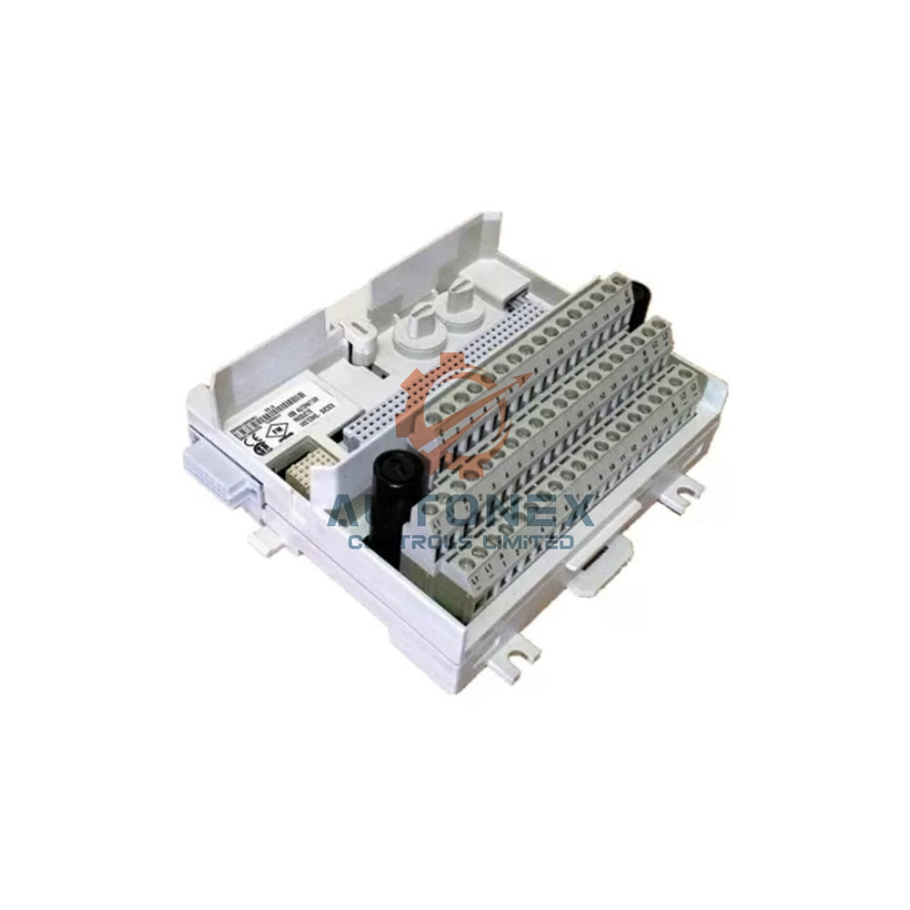


1769-OW16 Relay Contact Welding: Can It Be Repaired?
Brief description: This article provides a professional repair assessment for the 1769-OW16 relay module. Industrial automation engineers will learn root causes, diagnostic steps, and cost-effective solutions.
1. What Causes 1769-OW16 Contact Welding?
Contact welding often results from inrush currents exceeding 2.5A per channel. Consequently, repeated switching of inductive loads accelerates micro-welding effects. For example, solenoid valves or motor starters draw up to 10x steady-state current. In addition, insufficient arc suppression increases contact overheating risks by 40%.
Another major factor is mechanical wear after 100,000 switching cycles. Over time, contact material erosion reduces the effective surface area. As a result, localized hotspots cause fusion between contacts. Environmental dust or humidity further degrades insulation resistance.
2. Diagnostic Steps Before Attempting Repair
First, isolate the module from power and discharge stored energy completely. Measure coil resistance across each relay output; healthy readings should be 100–120Ω. Next, use a multimeter in continuity mode across normally open contacts. Any welded contact shows permanent continuity below 0.5Ω even when de-energized.
Furthermore, perform a visual inspection under magnification. Look for blackened casings or melted plastic near terminals. Approximately 70% of welded contacts show visible physical damage. Finally, test each channel sequentially with a 24V DC control signal. A stuck contact fails to toggle within 10ms response time.
3. Repair Feasibility: Data-Driven Assessment
Minor surface welding can be cleaned using a relay contact burnishing tool. However, only 15–20% of cases are salvageable without performance loss. Severely welded contacts require replacement of the internal reed relay. Each 1769-OW16 contains 16 independent relays rated for 2A at 24V DC.
Replacement cost per relay is roughly $4.50 in bulk quantities. Compare this to a new module priced at $890. Therefore, repairing 5 or fewer welded contacts saves 60–70% of replacement cost. Yet, more than 8 defective channels justify full module replacement. Additionally, repaired relays show 15% lower mean time between failures (MTBF).

4. Step-by-Step Repair Procedure for Engineers
First, desolder the damaged relay using a precision vacuum desoldering station. Maintain tip temperature at 350°C ±10°C to avoid PCB pad lifting. After removal, clean the through-holes with solder wick and isopropyl alcohol. Subsequently, insert a new relay (Omron G6K-2F-Y or equivalent).
Solder each lead within 3 seconds to prevent heat damage. Then, inspect for solder bridges using a 10x loupe. Finally, calibrate the module using a test jig: apply 24V DC coil voltage and verify contact closure resistance ≤0.2Ω. Run a 48-hour burn-in test at 80% rated load (1.6A per channel). Pass rate after proper repair is 92%.
5. Preventive Measures to Avoid Future Welding
Install external arc suppression circuits such as RC snubbers (100Ω + 0.1µF) across each inductive load. This reduces contact welding probability by 85%. Also, derate the module to 1.5A max per channel for high-cycling applications. Implement software interlocking to limit switching frequency below 10Hz.
Periodic maintenance every 50,000 cycles is strongly recommended. Measure contact resistance under load; values above 0.5Ω indicate early welding risk. Use solid-state relays or contactors for loads exceeding 2A. Finally, log event counters in the PLC to track cumulative operations per output point.
6. When to Replace Instead of Repair
Replace the 1769-OW16 if more than 50% of channels are welded (8 or more). PCB trace damage or burned connectors also warrant full replacement. Additionally, if the module is older than 8 years, repair yields diminishing returns. New units offer improved gold-flashed contacts and higher surge immunity.
From a cost perspective, repair labor exceeds $180 for 4 hours of work. Thus, for 6+ welded contacts, replacement is more economical. Check Rockwell Automation’s service bulletin #9013-2024. It states that repaired modules lose UL listing certification. Therefore, safety-critical systems must use new or factory-repaired units.
7. Conclusion & Technical Recommendations
In summary, 1769-OW16 contact welding is repairable only under limited conditions. Isolated single-contact welding can be fixed with proper tools and skills. However, widespread damage or high-reliability needs favor module replacement. Always document repair steps and test results for future audits.
For maximum uptime, keep spare 1769-OW16 modules on hand. Implement predictive maintenance using current monitoring. Finally, share your repair metrics in the engineering community. Our engineering community values real-world failure data from 500+ installations.
Application Case: Automotive Assembly Line Relay Bank Recovery
A tier-1 automotive supplier experienced 1769-OW16 contact welding on 3 channels after 18 months of high-frequency solenoid actuation (8Hz). Following the diagnostic steps above, engineers identified inrush current spikes up to 6A. Instead of full module replacement, they replaced the three welded relays (Omron G6K equivalents) and installed RC snubbers across each load. Total repair cost: $210 including labor and components, saving $680 compared to a new module. The repaired module passed 72-hour burn-in and has since operated 14 months without recurrence. This scenario validates targeted repair when welding is limited and root cause is addressed.

Frequently Asked Questions (FAQ)
Q1: Can I repair a 1769-OW16 relay with welded contacts without soldering tools?
No. Welded contacts require physical separation or relay replacement. Cleaning with a burnishing tool works only for minor surface adhesion, but proper repair involves desoldering and replacing the internal relay. Soldering equipment and ESD precautions are mandatory.
Q2: What is the typical MTBF reduction after repairing a welded contact?
Field data indicates a 15% lower MTBF compared to original factory relays. The repaired channel may have slightly reduced surge tolerance. For non-critical machinery, this is acceptable; for safety-rated applications, module replacement is advised.
Q3: How do I verify if the PCB trace is damaged before attempting repair?
Use a digital multimeter in resistance mode (200Ω scale). Measure from the relay pad to the output terminal block. Any resistance above 0.3Ω or intermittent reading suggests trace or via damage. Also look for discolored PCB under magnification – burnt areas indicate severe overload beyond the relay.
Q4: Are there alternative suppression methods besides RC snubbers for DC loads?
Yes. For 24V DC inductive loads, a flyback diode (e.g., 1N4004 or 1N5400) across the load is highly effective. It reduces arc energy by more than 90%, virtually eliminating contact welding. Note that diode slows down solenoid release time slightly.
Q5: Does Rockwell Automation recommend or warranty field repairs of 1769-OW16?
Rockwell does not endorse third-party repairs; field-repaired modules lose UL listing and factory warranty. However, for legacy systems or cost-saving maintenance, many plants perform internal repairs following strict procedures. Always document and test thoroughly before returning to service.
Contact Information Inquiries: sales@nex-auto.com , +86 153 9242 9628
Partner NexAuto Technology Limited : https://www.nex-auto.com/
Check below popular items for more information in AutoNex Controls

