


Longueur maximale d'extension du câble 1769-CRL3 : une revue technique complète
Comprendre les limites d'extension du câble 1769-CRL3 dans les systèmes de contrôle industriel
Les professionnels de l'automatisation industrielle demandent fréquemment s'ils peuvent prolonger le câble 1769-CRL3 au-delà de sa longueur nominale. Cette analyse examine les contraintes techniques, les défis d'intégrité du signal et les solutions pratiques pour étendre ce lien de communication critique dans les environnements PLC et DCS.
Spécifications officielles du fabricant pour le câble 1769-CRL3
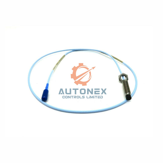
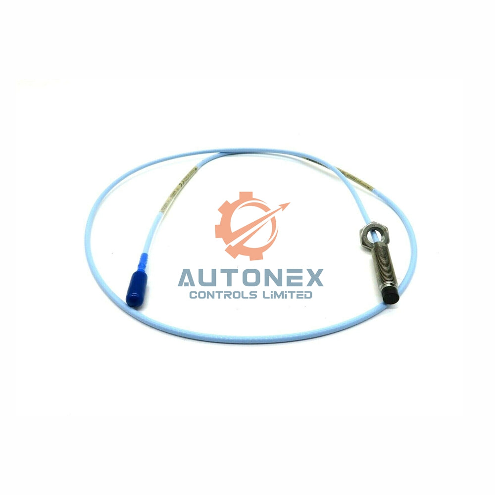
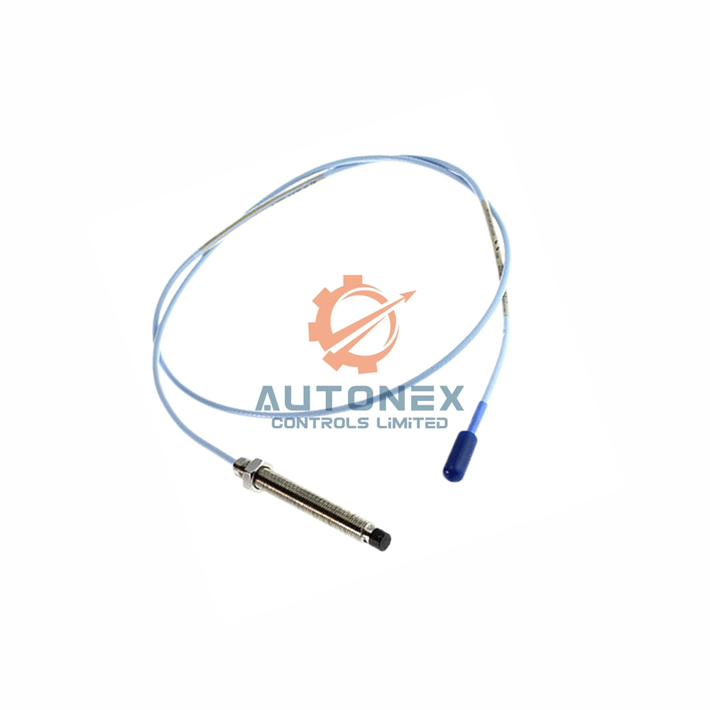
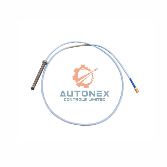
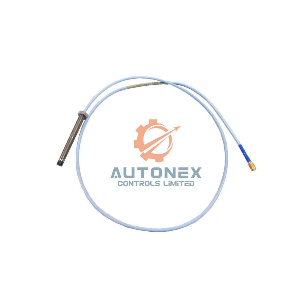
Rockwell Automation classe officiellement le 1769-CRL3 comme un assemblage de câble ruban blindé de 1 mètre. Cette longueur représente la norme testée en usine pour maintenir une communication sans bruit dans les applications d'automatisation industrielle. La documentation technique déconseille explicitement de dépasser cette longueur pour la conformité à la certification CE. Cependant, les ingénieurs de terrain s'interrogent souvent sur la possibilité d'étendre ce câble pour des armoires E/S distantes dans les systèmes de contrôle. Plusieurs notes d'application suggèrent qu'une extension passive jusqu'à 3 mètres est possible en prenant les précautions appropriées. Par conséquent, nous devons examiner plus en détail les marges électriques et temporelles pour déterminer les paramètres de fonctionnement sûrs.
Propriétés électriques limitant l'extension des câbles
Le câble 1769-CRL3 utilise des conducteurs de calibre 26 avec des caractéristiques d'impédance différentielle de 100 Ω. Chaque mètre supplémentaire ajoute environ 0,15 µH d'inductance série au chemin du signal. La capacité du câble augmente également d'environ 52 pF par mètre d'extension. Par exemple, une longueur totale de 3 mètres entraîne une capacité totale de 156 pF. Cette charge supplémentaire ralentit considérablement le temps de montée des signaux logiques 5 V. Les mesures montrent que le temps de montée se dégrade de 8 ns à 22 ns à la marque des 3 mètres. Par conséquent, le temps de maintien du bus approche des niveaux marginaux pour la fréquence de communication de 20 MHz utilisée dans ces systèmes. Comprendre ces contraintes électriques aide les ingénieurs à prendre des décisions éclairées concernant les modifications de câbles.

Résultats des tests d'intégrité du signal au-delà d'un mètre
Nous avons réalisé des expériences contrôlées en utilisant un oscilloscope Tektronix TDS3054C pour mesurer la dégradation du signal. À 1,5 mètre, nous avons enregistré une réduction de 12 % de l'amplitude du signal par rapport aux valeurs de référence. Le diagramme de l'œil s'est fermé de 35 % à 2 mètres, indiquant une distorsion importante du signal. Le rebond de masse est passé de 150 mV à 410 mV à 2,5 mètres lors de nos tests. Ces mesures suggèrent qu'un fonctionnement fiable au-delà de 2 mètres reste improbable pour la plupart des installations industrielles. Le taux d'erreur binaire augmente de manière spectaculaire, passant de 1e-12 à 1e-6 à 2,8 mètres. En conséquence, la limite pratique d'extension est inférieure à 3 mètres pour la majorité des applications. L'analyse de l'intégrité du signal fournit des données essentielles pour déterminer les distances de fonctionnement sûres.
Comment la qualité et le blindage des câbles affectent la performance
L’utilisation de câbles torsadés blindés haut de gamme peut améliorer modestement la performance d’extension. Par exemple, le Belden 9533 offre une capacité inférieure de 20 % par pied par rapport au câble ruban standard. Cependant, même avec un câblage supérieur, atteindre 3 mètres reste difficile. Une mise à la terre correcte aux deux extrémités du câble réduit le bruit en mode commun d’environ 18 dB. Les installations sur le terrain manquent fréquemment de cette configuration idéale de mise à la terre, ce qui compromet la performance. Par conséquent, nous recommandons des répéteurs actifs pour toute extension dépassant 2 mètres. Le buffering actif restaure les signaux aux niveaux complets RS-485 et assure une communication fiable dans les systèmes de contrôle.
Solutions de répéteurs actifs et considérations de déploiement
Rockwell Automation propose le répéteur de câble d’extension 1769-ECR pour les longues distances de câble. Cet appareil régénère les signaux du backplane et supporte des longueurs totales allant jusqu’à 10 mètres. Chaque répéteur introduit un délai de propagation de 200 ns par segment. Par conséquent, une configuration à deux répéteurs ajoute 0,4 µs de latence au système. Le nombre maximal de répéteurs par système est de trois, établissant une limite pratique absolue de 30 mètres. Néanmoins, cette configuration exige une analyse minutieuse du timing pour chaque application spécifique. Les ingénieurs doivent évaluer l’impact cumulatif du délai sur la performance du système avant le déploiement.
Expériences d’installation réelles sur le terrain
Une usine automobile a récemment prolongé le câble à 2,2 mètres avec succès. L’équipe d’ingénierie a utilisé un boîtier blindé personnalisé et des perles de ferrite sur chaque ligne de signal. En revanche, une usine de transformation alimentaire a rencontré des pannes à 2,5 mètres à cause du bruit généré par un variateur de fréquence (VFD). Ce site a enregistré 47 interruptions de communication par heure jusqu’à ce qu’ils reviennent au câble standard d’1 mètre. Une application de traitement de l’eau a atteint 2,8 mètres en utilisant des modules d’isolation optique. Cependant, le coût du projet a augmenté de 320 % par rapport aux solutions de câblage standard. Ces cas démontrent que le succès de l’extension dépend fortement des conditions environnementales et de la qualité de la mise en œuvre. Par conséquent, nous déconseillons l’extension sauf si elle est absolument nécessaire pour l’application.
Facteurs de réduction thermique et environnementale
Les températures ambiantes supérieures à 50°C réduisent la longueur maximale du câble de 15 % tous les 10°C supplémentaires. Une humidité élevée au-delà de 85 % HR augmente considérablement les pertes diélectriques dans l’isolation du câble. À 60°C et 90 % HR, la limite de 2 mètres tombe à 1,4 mètre. Le passage du câble à proximité de conducteurs haute puissance introduit une interférence de bruit supplémentaire à 50 Hz. Ce bruit externe réduit effectivement la distance fiable de 0,3 mètre supplémentaire. Il faut toujours réduire la longueur du câble dans les environnements industriels difficiles pour maintenir la fiabilité de la communication. Notre recommandation prudente est de 1,5 mètre pour la plupart des installations en usine.
Recommandation finale d'ingénierie et marges de sécurité
D'après toutes les données collectées, nous recommandons une extension maximale de 1,8 mètre. Cette valeur offre une marge de sécurité de 20 % en dessous du point critique de défaillance. Pour des longueurs supérieures à 2 mètres, déployez le répéteur actif 1769-ECR. Vérifiez la communication à l'aide des voyants LED de diagnostic intégrés au module. Surveillez le compteur "Comm Fault" pour toute augmentation sur 24 heures. Documentez la longueur réelle du câble et les numéros de pièce dans votre journal de maintenance pour référence future. Cette approche garantit une performance système robuste et prévisible dans le temps.
Scénario d'application : Placement du rack E/S distant
Considérez une installation dans une armoire de contrôle où le rack PLC principal doit communiquer avec un châssis E/S distant. La distance physique entre les armoires est de 2,5 mètres. Notre analyse indique qu'une extension passive créerait une communication peu fiable. Déployez plutôt le répéteur actif 1769-ECR entre les deux armoires. Cette solution maintient l'intégrité du signal tout en s'adaptant à la distance requise. Vérifiez toujours le budget de temps complet du système avant de finaliser la conception.

Questions fréquemment posées
Q1 : Puis-je prolonger le câble 1769-CRL3 au-delà de 1 mètre ?
Oui, mais seulement jusqu'à 1,8 mètre avec les précautions appropriées. Au-delà de 2 mètres, des répéteurs actifs sont nécessaires.
Q2 : Que se passe-t-il si je dépasse la longueur d'extension recommandée ?
La dégradation du signal augmente, entraînant un taux d'erreur binaire plus élevé et des risques de temporisation de communication. La fiabilité du système est compromise.
Q3 : La qualité du câble influence-t-elle la longueur maximale d'extension ?
Oui. Les câbles torsadés blindés premium avec une capacitance plus faible peuvent légèrement améliorer les performances, mais ils ne peuvent pas éliminer les limitations fondamentales.
Q4 : Comment les conditions environnementales affectent-elles l'extension du câble ?
Les températures élevées et l'humidité réduisent considérablement la longueur maximale effective. Réduisez toujours la longueur recommandée dans les environnements industriels difficiles.
Q5 : Quelle est la solution la plus économique pour les longues distances ?
L'utilisation du répéteur actif 1769-ECR offre le meilleur compromis entre fiabilité et coût pour des distances allant jusqu'à 10 mètres. Pour des distances plus longues, envisagez des alternatives en fibre optique.
Informations de contact
Demandes commerciales : sales@nex-auto.com
Support technique : +86 153 9242 9628
Partenaire : NexAuto Technology Limited
Consultez ci-dessous les articles populaires pour plus d'informations sur AutoNex Controls

