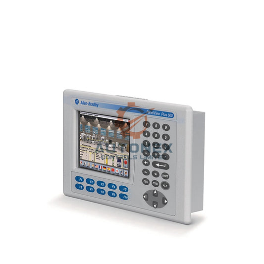
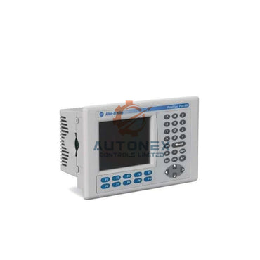
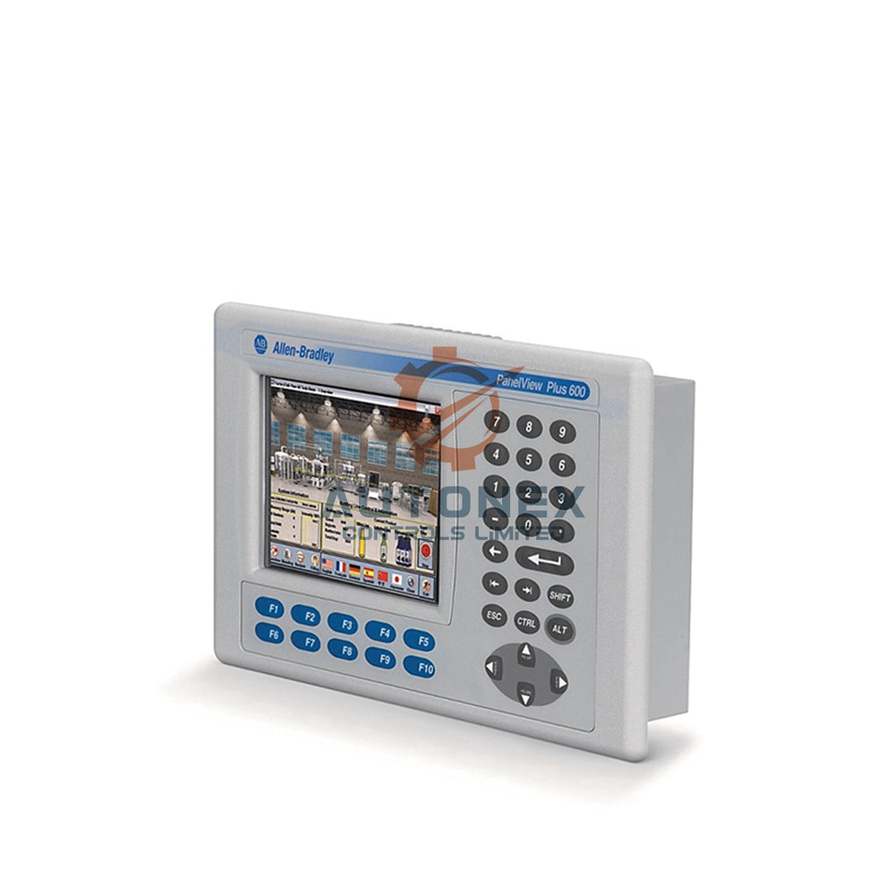


1769-OF4 Modullarında Şiddətli Analoq Çıxış Səsini Necə Azaltmaq Olar
Analoq siqnallarda güclü dalğalanmalar proses idarəetməsini pozur. Bir çox mühəndis 1769-OF4 modulundan qeyri-sabit çıxışlarla üzləşir. Bu bələdçi ±5%-dən ±0.5%-ə qədər səsi azaltmaq üçün təsdiqlənmiş üsulları paylaşır. Siz sənaye avtomatlaşdırma sistemləri üçün aparat filtrləri, proqram təminatı ortalaması və düzgün torpaqlama öyrənəcəksiniz.
1. Siqnal Səsinin Əsl Mənbəyini Müəyyən Edin
Elektrik müdaxiləsi tez-tez təsadüfi çıxış dalğalanmalarına səbəb olur. Yaxınlıqda olan dəyişkən tezlik sürücüləri (VFD) bir çox zavodda ±3.2% dalğalanma yaradır. Digər tez-tez rast gəlinən mənbə ağır maşınlarla paylaşılan 0 VDC istinadıdır. Həmişə əvvəlcə boş terminal bloklarını və zədələnmiş kabelləri yoxlayın.
2. Hər Kanal üçün Daxili Aşağı Keçid Filtrini Aktivləşdirin
1769-OF4 proqramlaşdırıla bilən rəqəmsal filtrə malikdir. Əksər idarəetmə sistemləri üçün kəsim tezliyini 2 Hz ilə 60 Hz arasında təyin edin. Ümumi proseslər üçün 10 Hz parametri yaxşı işləyir. Bu addım yüksək tezlikli səsin təxminən 70%-ni çıxarır, addım dəyişikliklərini çox yavaşlatmadan. Hər kanalı asanlıqla tənzimləmək üçün RSLogix 5000 istifadə edin.

3. Pilləli Loqikanızda Hərəkətli Orta Qurun
Xüsusi hərəkətli orta qiymət qeyri-sabit siqnalları effektiv şəkildə yumşaldır. Hər 50 millisekundda son səkkiz nümunənin ortalamasını alın. Sahə testləri göstərir ki, bu, titrəməni ±1.2%-dən ±0.3%-ə azaldır. Tarixi dəyərləri massivdə saxlayın. PID dövrənizin süzülmüş yeniləmə sürətindən yavaş işlədiyinə əmin olun.
4. Tək Uclu Torpaqlama ilə Qorunan Burulmuş Cüt Kabellərdən İstifadə Edin
Qorunan kabellər ümumi rejim səsini 85%-ə qədər azaldır. Drenaj naqilini yalnız 1769-OF4 yaxınlığında şassi torpağına qoşun. Hər iki ucu torpaqlamayın. Bu, torpaq dövrlərinin qarşısını alır. Analoq kabelləri AC güc naqillərindən ən azı 15 sm uzaqda saxlayın. Bir zavod yalnız bu dəyişikliklə ±4.1% dalğalanmanı həll etdi.
5. Analoq Modul üçün Güc Təchizatını İzolyasiya Edin
Xüsusi 24 VDC təchizatı digər cihazlardan gələn keçid səsini dayandırır. Paylaşılan təchizatlar çıxışa təsadüfi sıçrayışlar əlavə edir. Son testdə izolyasiya dəyişkənliyi ±2.8%-dən ±0.4%-ə iki saat ərzində azaltdı. 1 MHz-dən yuxarı əlavə sönüm üçün DC giriş naqillərinə ferrit nüvəsi əlavə edin.
6. İdarəetmə Loqikasında Ramp Sürət Məhdudlaşdırıcısı Tətbiq Edin
Ani setpoint sıçrayışları real dalğalanmalara bənzəyə bilər. Dəyişiklikləri skan başına 1% ilə məhdudlaşdırmaq üçün ramp məhdudlaşdırıcısı proqramlaşdırın. Məsələn, əmr 20% sıçrayırsa, çıxış ona çatmaq üçün 20 skan alır. Bu aktuator cavabını yumşaldır və klapan səs-küyünü önləyir. Həmçinin yüksək tezlikli pozuntuları effektiv gizlədir.
7. Yük İmpedansını və Kabelləşmə Konfiqurasiyasını Yoxlayın
1769-OF4 0–20 mA və ya 4–20 mA dəstəkləyir, maksimum 750 Ω yükə qədər. 600 Ω-dan çox keçmək sabitliyi pozur. Bir mühəndis 820 Ω-da 1.8% sinus dalğası ölçdü, 500 Ω-da yox oldu. 150 metrdən uzun qorunmayan kabeldən qaçının. Ən yaxşı səs-küy müqaviməti üçün dövrə müqavimətini 500 Ω-dan aşağı saxlayın.
8. İllik Kalibrləmə və Diaqnostik Bitlərin İzlənməsi
Zamanla sürüşmə ildə 1.2%-ə qədər çıxış dəyişikliklərinə səbəb olur. Hər 12 ayda dəqiq cərəyanölçənlə kalibrləyin. Kontrollerinizdə modulun diaqnostik status bitlərini oxuyun. Aşırı və ya az diapazon bayrağı çox vaxt kabelləşmə problemini göstərir, filtr problemini yox. Sadə kalibrləmə bir halda 5% sürüşməni düzəltdi.
9. Lazımsız Yeniləmələri Azaltmaq üçün Proqram Ölü Zonası Əlavə Edin
Ölü zona kiçik dəyişikliklərin səs-küy yaratmasının qarşısını alır. Analoq çıxış rutininizdə 0.2% ölü zona təyin edin. Yalnız fərq 20 mA diapazonu üçün 80 µA-dan çoxdursa yeni dəyər göndərin. Bir qablaşdırma xətti bu texnika ilə klapan hərəkətlərini dəqiqədə 180-dən 4-ə endirdi.

10. Trend Qrafikləri ilə Əsas Səbəb Analizini Aparın
Hər 100 ms-də xam əmri və faktiki cərəyanı qeyd edin. Səs-küy təsadüfi görünür; osilləyişlər PID tənzimləmə problemlərinə işarə edir. Bir sement zavodunda 0.8 Hz osilləyiş səs-küy kimi görünürdü. PID yenidən tənzimləndikdən sonra dalğalanma ±3.4%-dən ±0.25%-ə düşdü. Həmişə mürəkkəb filtrlər əlavə etməzdən əvvəl trendə baxın.
Sahədən Son Tövsiyə
Daxili 10 Hz filtri və qorunan kabelləşmə ilə başlayın. Sonra məntiqdə 8 nümunəli hərəkətli ortanı əlavə edin. Bu üç tədbir sənaye ssenarilərinin 90%-ində tipik dalğalanmaları ±5%-dən ±0.5%-dən aşağı salır. Dəyişikliklərdən əvvəl və sonra həmişə trend qrafiki ilə təsdiqləyin.
Müəllif Baxışı: Niyə Hibrid Filtrləmə Qalib Gəlir
Heç bir tək üsul bütün səs-küy problemlərini həll etmir. Aparat filtrlərini proqram məntiqi ilə birləşdirmək ən yaxşı nəticəni verir. Bir çox mühəndis həlləri çox mürəkkəbləşdirir. Sadə başlayın. Daxili filtr yüksək tezlikləri aradan qaldırır. Hərəkətli orta isə təsadüfi sıçrayışları idarə edir. Bu hibrid yanaşma saatlarla problemlərin aradan qaldırılmasını qənaət edir.
Təcrübəmə görə, torpaqlama səhvləri bütün dalğalanma şikayətlərinin yarısını təşkil edir. Həmişə əvvəlcə qalxan bağlantısını yoxlayın. Fabrikdəki naqillərə kor-koranə inanmayın. Tez bir vizual yoxlama tez-tez paylaşılan kanallar və ya çatışmayan drenaj naqillərini aşkar edir.
Tətbiq Ssenarisi: Sement Zavodunun Uğur Hekayəsi
Bir sement zavodu torba toz nəzarət damperində ±4.8% dalğalanmalarla üzləşdi. 1769-OF4 çıxışı 4-20 mA mövqe tənzimləyicisini idarə edirdi. 10 Hz filtr, qalxanlı kabel və 8 nöqtəli hərəkətli ortalama tətbiq edildikdən sonra dalğalanma ±0.3%-ə düşdü. Zavod bahalı modul dəyişməsindən qaçdı və texniki xidmət zənglərini 90% azaltdı.
Ümumi İdarəetmə Sistemləri üçün Həll
Bu strategiya 1769-OF4 istifadə edən hər hansı PLC və ya DCS ilə işləyir. Rockwell Automation CompactLogix və ControlLogix platformaları üçün oxşar təcrübələri tövsiyə edir. Prinsiplər hər hansı analoq çıxış modulunda elektrik səs-küyü və ya zəif torpaqlama ilə qarşılaşdıqda tətbiq olunur.
Tez-tez verilən suallar (FAQ)
1. 1769-OF4 üçün səs-küyü önləmək üçün maksimum yük nə qədərdir?
Yükü 600 Ω-dan aşağı saxlayın. Modul 750 Ω-a qədər dəstəkləyir, amma 600 Ω-dan yuxarı dəyərlər dalğalanmaya səbəb ola bilər. Optimal səs-küy müqaviməti üçün 500 Ω hədəfləyin.
2. Qalxanlı kabelin hər iki ucunu torpaqlaya bilərəmmi?
Xeyr. Yalnız modul ucunda torpaqlayın. Hər iki ucu torpaqlamaq torpaq dövrələri yaradaraq analoq siqnalda səs-küy yaradır.
3. 1769-OF4-ü nə qədər tez-tez kalibrləməliyəm?
Hər 12 ayda bir kalibrləyin. Sürüşmə ildə 1.2%-ə çata bilər, bu da proses dəqiqliyinə təsir edir. Ən yaxşı nəticə üçün dəqiq cərəyan ölçən istifadə edin.
4. Hərəkətli ortalama PID dövrəmi yavaşladırmı?
Bəli, bir az. PID dövrəsinin süzülmüş yeniləmə sürətindən yavaş işlədiyinə əmin olun. 8 nümunəlik tamponla 50 ms hərəkətli ortalama təxminən 400 ms gecikmə əlavə edir, bu da əksər proseslər üçün qəbul ediləndir.
5. Təsadüfi çıxış dalğalanmaları üçün ilk yoxlanılacaq nədir?
0 VDC istinadını və torpaqlamanı yoxlayın. VFD-lər və ya mühərriklərlə paylaşılan qayıdış yolu ən çox rast gəlinən səbəbdir. Terminal bloklarını və kabel qalxanlarını dərhal yoxlayın.
Sorğular və ya texniki dəstək üçün:
Email: sales@nex-auto.com
WhatsApp: +86 153 9242 9628
NexAuto Technology Limited tərəfdaşı: https://www.nex-auto.com/
Daha ətraflı məlumat üçün aşağıdakı məşhur məhsullara AutoNex Controls saytında baxın

